Title here
Summary here
Building a custom PetaLinux image for the ZedBoard with four extra Ethernet ports via Ethernet FMC.
May 4, 20169 minutes
Many FPGA-based embedded designs require connections to multiple Ethernet devices such as IP cameras, and control of those devices under an operating system, typically Linux. The development of such applications can be accelerated through the use of development boards such as the ZedBoard and the Ethernet FMC. In this tutorial, we will build a custom version of PetaLinux for the ZedBoard and bring up 4 extra Ethernet ports, made available by the Ethernet FMC. The Vivado hardware design used in this tutorial will be very similar to the one we created in a previous tutorial titled: Using AXI Ethernet Subsystem and GMII-to-RGMII in a Multi-port Ethernet design. You don’t need to have followed that tutorial to do this one, as the Vivado project can be built from the sources on Github.
To complete this tutorial you will need the following:
PetaLinux SDK 2015.4 only runs in the Linux operating system, so Windows users (like me) have to have two machines to follow this tutorial. You can either have two physical machines, which is how I work, or you can have one Windows machine and one Linux virtual machine. In this tutorial, I will assume that you have two physical machines, one running Windows and the other running Linux. My personal setup uses Windows 7 and Ubuntu 14.04 LTS on two separate machines.
If you are building your Linux setup for the first time, here are the supported OSes according to the PetaLinux SDK Installation guide:
Note: I had problems installing PetaLinux SDK 2015.4 on 32-bit Ubuntu, as did others, so I use 64-bit Ubuntu and I haven’t had any problems with my setup.
The details of the Vivado design will not be covered by this tutorial as it has already been covered in a previous tutorial - except that in this tutorial, we will be using AXI Ethernet Subsystem IP for all 4 ports. Follow these instructions to regenerate the Vivado project from scripts. Please note that the Git repository is regularly updated for the latest version of Vivado, so you must download the last “commit” for the version of Vivado that you are using.
build.bat file to run the batch file.source build.tcl to run the build script.
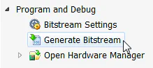
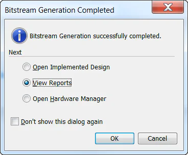
The first thing we’ll need to do is to generate the bitstream from the Vivado project.
Now it’s time to move to our Linux machine and use the PetaLinux SDK to build PetaLinux for our hardware design.
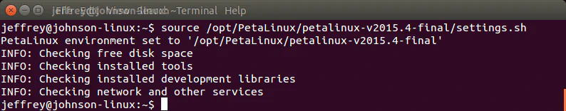
On your Linux machine, start a command terminal.
Type source /<your-petalinux-install-dir>/settings.sh into the terminal and press Enter. Obviously you must insert the location of your PetaLinux installation.
For consistency, let’s work from a directory called projects/zedboard-multiport-ethernet in your home directory. Create that directory and then “cd” to it.
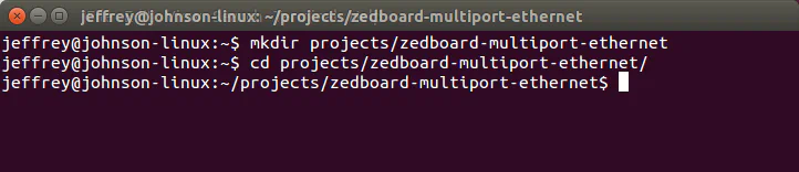
Use a USB stick or another method to copy the entire Vivado project directory (should be zedboard_qgige_axieth) from your Windows machine onto your Linux machine. Place it into the directory we just created.
Create a PetaLinux project using this command: petalinux-create --type project --template zynq --name petalinux_prj
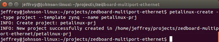
Change to the “petalinux_prj” directory in the command terminal.
Stay in the PetaLinux project folder from here on. It is important that all the following commands are run from the PetaLinux project folder that we just created.
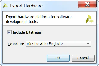
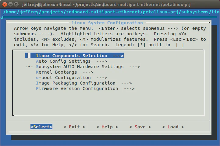
Import the Vivado generated hardware description into our PetaLinux project with the command: petalinux-config --get-hw-description ../zedboard_qgige_axieth/zedboard_qgige_axieth.sdk/
The Linux System Configuration will open, but we don’t have any changes to make here, so simply exit and save the configuration.
Configure the Linux kernel with the command: petalinux-config -c kernel
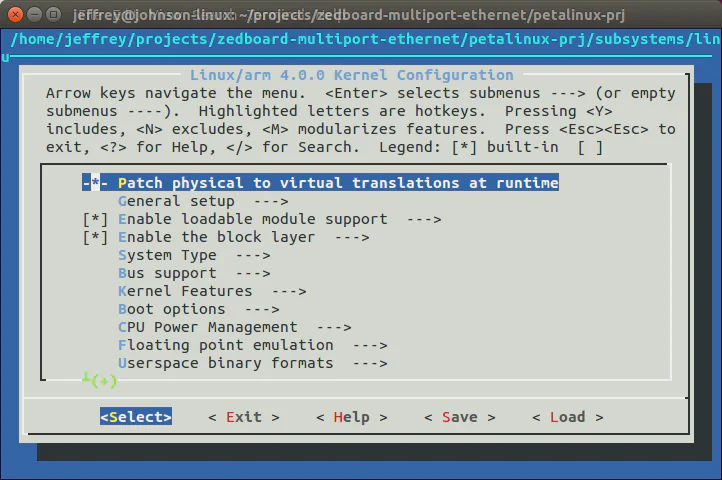
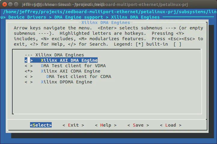
In the Kernel configuration, we need to disable the Xilinx AXI DMA driver, as it conflicts with the AXI Ethernet driver. Disable: Device Drivers->DMA Engine support->Xilinx DMA Engines->Xilinx AXI DMA Engine, then exit and save the configuration.
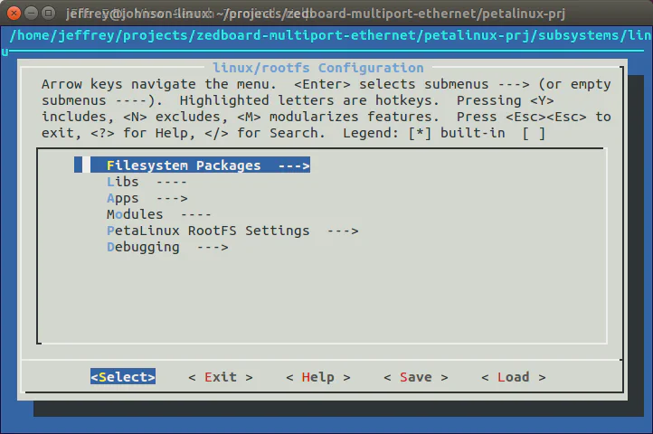
We don’t have anything to change in the Linux root file system, but if you want to make your own changes, run the command: petalinux-config -c rootfs
The device tree that was generated by PetaLinux SDK will not contain the MAC addresses, nor the addresses of the Ethernet PHYs, so we have to add this information manually. Open the system-top.dts file in the petalinux-prj/subsystems/linux/configs/device-tree directory.
system-user.dtsi file located under project-spec/meta-user/recipes-bsp/device-tree/files.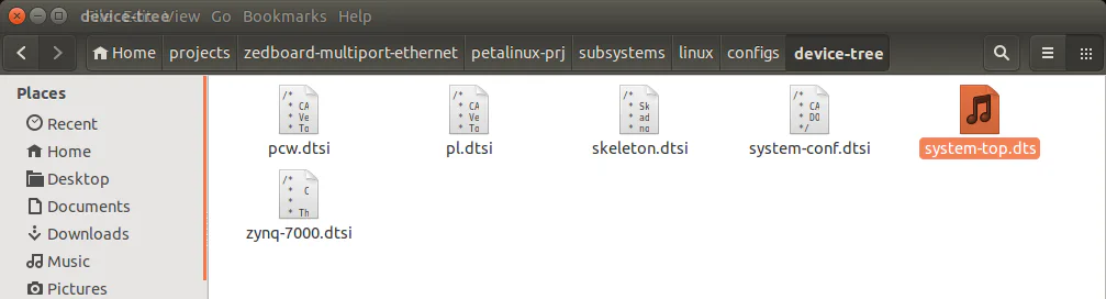
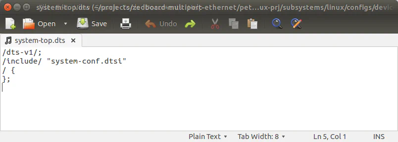
Add the following code to the end of the system-top.dts file and then save it:
&axi_ethernet_0 {
    local-mac-address = [00 0a 35 00 01 22];
    phy-handle = <&phy0>;
    xlnx,has-mdio = <0x1>;
    phy-mode = "rgmii-rxid";
    mdio {
        #address-cells = <1>;
        #size-cells = <0>;
        phy0: phy@0 {
            compatible = "marvell,88e1510";
            device_type = "ethernet-phy";
            reg = <0>;
        };
    };
};

&axi_ethernet_1 {
    local-mac-address = [00 0a 35 00 01 23];
    phy-handle = <&phy1>;
    xlnx,has-mdio = <0x1>;
    phy-mode = "rgmii-rxid";
    mdio {
        #address-cells = <1>;
        #size-cells = <0>;
        phy1: phy@0 {
            compatible = "marvell,88e1510";
            device_type = "ethernet-phy";
            reg = <0>;
        };
    };
};

&axi_ethernet_2 {
    local-mac-address = [00 0a 35 00 01 24];
    phy-handle = <&phy2>;
    xlnx,has-mdio = <0x1>;
    phy-mode = "rgmii-rxid";
    mdio {
        #address-cells = <1>;
        #size-cells = <0>;
        phy2: phy@0 {
            compatible = "marvell,88e1510";
            device_type = "ethernet-phy";
            reg = <0>;
        };
    };
};

&axi_ethernet_3{
    local-mac-address = [00 0a 35 00 01 25];
    phy-handle = <&phy3>;
    xlnx,has-mdio = <0x1>;
    phy-mode = "rgmii-rxid";
    mdio {
        #address-cells = <1>;
        #size-cells = <0>;
        phy3: phy@0 {
            compatible = "marvell,88e1510";
            device_type = "ethernet-phy";
            reg = <0>;
        };
    };
};phy-mode in the above code to "rgmii-id".petalinux-buildPetaLinux will take a few minutes to build depending on your machine.
Now we will generate the boot files for an SD card, copy those files to the SD card and then boot PetaLinux on the ZedBoard.
petalinux-package --boot --fsbl ./images/linux/zynq_fsbl.elf --fpga ../zedboard_qgige_axieth/zedboard_qgige_axieth.runs/impl_1/design_1_wrapper.bit --uboot --forcepetalinux-package --prebuilt --fpga ../zedboard_qgige_axieth/zedboard_qgige_axieth.runs/impl_1/design_1_wrapper.bit
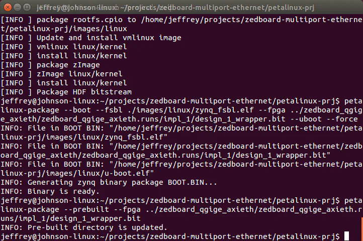
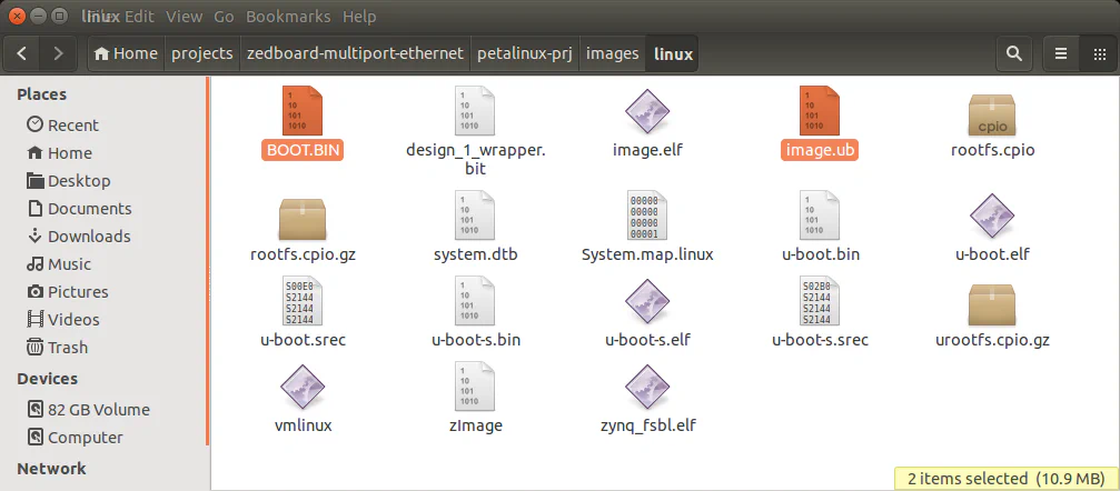
petalinux-prj/images/linux folder. Copy the BOOT.BIN and image.ub files into the root of your SD card.
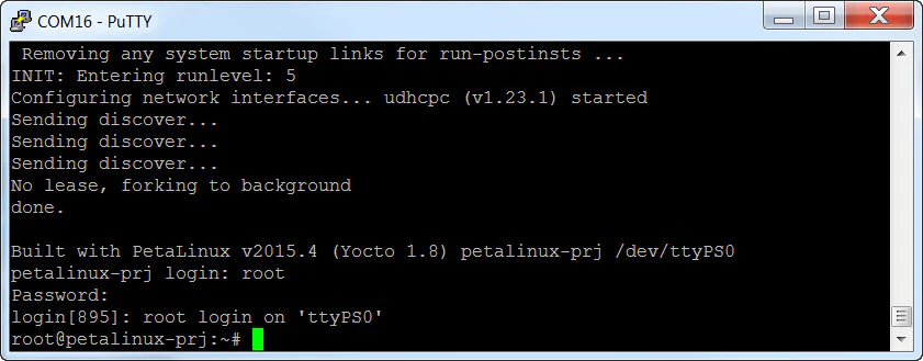
If you want to see the complete boot log, click here.
Our Vivado design has 5 Ethernet ports: the on-board port of the ZedBoard plus the 4 ports of the Ethernet FMC. In PetaLinux, these ports will be assigned to eth0 (on-board port), and eth1-eth4 (Ethernet FMC ports 0-3). Using ifconfig, we will configure the Ethernet FMC ports with fixed IP addresses. We will then connect one of them to a PC and use ping to test it.
ifconfig eth1 192.168.1.11 netmask 255.255.255.0 upifconfig eth2 192.168.1.12 netmask 255.255.255.0 upifconfig eth3 192.168.1.13 netmask 255.255.255.0 upifconfig eth4 192.168.1.14 netmask 255.255.255.0 up
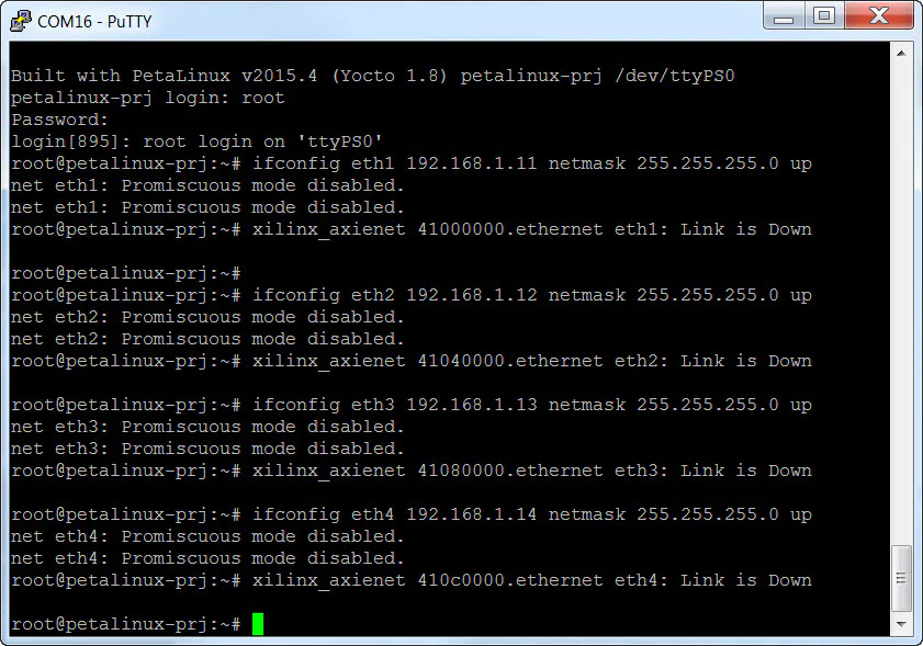
net eth1: Promiscuous mode disabled.
net eth1: Promiscuous mode disabled.
xilinx_axienet 41000000.ethernet eth1: Link is Down
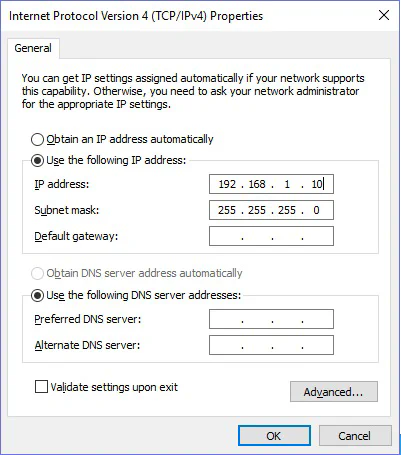
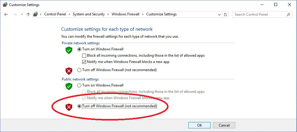
To test the Ethernet ports, we’ll need a PC with it’s own gigabit Ethernet port. Here I’m using my laptop which runs on Windows 10.
xilinx_axienet 41000000.ethernet eth1: Link is Up - 1Gbps/Full - flow control off
ping 192.168.1.11
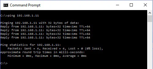
ping -I eth1 192.168.1.10
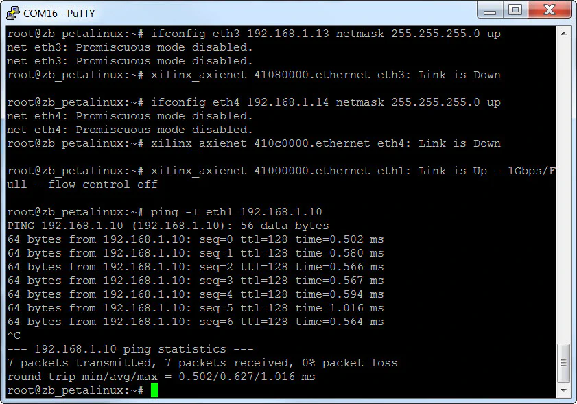
You will have to press Ctrl-C to stop pinging. Notice that we have to use the argument “-I eth1” from the ZedBoard as there are multiple ports we could possibly ping from. We can do the same ping test to verify the other ports.
The sources for re-generating this project automatically can be found on Github here: ZedBoard Multi-port Ethernet design
If you want to try out my boot files for the ZedBoard, download them here:
If you run into problems going through these instructions, just write me a comment below.