Title here
Summary here
Docker, Ubuntu and PetaLinux put to the test
July 10, 202310 minutes

Many smart vision applications need to make fast decisions: autonomous vehicles, drones, surveillance and industrial robotics are only a few examples. When developing these kinds of AI vision systems, understanding performance-affecting factors is critical.
In this post, we’ll explore two such factors: the operating system and camera type. We’ll measure and compare the performance of the NLP-SmartVision app on the ZCU104 board. The setups we’ll use are:
To assess performance, we’ll measure two aspects: frame rate and glass-to-glass latency. For the frame rate, we are going to use on the application’s own ability to measure frame rate. For the glass-to-glass latency, we are going to use a method that involves placing an LED in front of the camera and a detector in front of the monitor. The latency is measured as the time lag between the input and output signals of this system.
We’ll start off with the results and then in the next sections I’ll show you how I got them.
| OS | Face detect | Object detect | Plate detect |
|---|---|---|---|
| PetaLinux | 30 fps | 25 fps | 30 fps |
| Ubuntu | 30 fps | 25 fps | 30 fps |
| Ubuntu+Docker | 30 fps | 25 fps | 30 fps |
Note that the MIPI camera was operating at a frame rate of 30 fps in all of the above tests. The results of the face and plate detection tests suggest that we could have operated the camera at a higher frame rate to achieve an even higher throughput. The results of the object detection suggest that 25 fps is the maximum throughput for this implementation at this resolution.
| OS | Face detect | Object detect | Plate detect |
|---|---|---|---|
| PetaLinux | 24 fps | 24 fps | 24 fps |
| Ubuntu | 24 fps | 24 fps | 24 fps |
| Ubuntu+Docker | 24 fps | 24 fps | 24 fps |
Note that the USB camera was operating at a frame rate of 24 fps in all of the above tests. The results suggest that we could have operated the camera at a higher frame rate to achieve even higher throughputs.
Below are the glass-to-glass latency measurements. Rather than showing an average value for latency, I’ve listed them as a minimum and maximum value. The reason for this is that a variation in latency is to be expected due to the frame rate and the signal generator not being synchronous with the camera’s frame clock. To explain, consider this: we used the MIPI camera at a frame rate of 30 fps, that’s 33 milliseconds between frames. The LED OFF-to-ON transition can occur at any time within that 33ms window, and it will drift in time because it is asynchronous to the camera’s frame clock. If the LED happens to turn on towards the end of that window, say the end of the exposure time, or during the readout phase, it would not show up in that frame, leading us to see the LED transition occur in the next frame, 33ms later. In this system, a few milliseconds of difference on the input timing can lead to a 33 millisecond difference in the output timing.
| OS | Face detect | Object detect | Plate detect |
|---|---|---|---|
| PetaLinux | 96-120 | 240-270 | 96-120 |
| Ubuntu | 104-128 | 200-240 | 88-128 |
| Ubuntu+Docker | 104-124 | 200-280 | 100-128 |
To provide some sort of baseline for these measurements, I did two more tests:
| OS | No AI |
|---|---|
| Standalone | 31-64 |
| PetaLinux GStreamer | 140-190 |
| OS | Face detect | Object detect | Plate detect |
|---|---|---|---|
| PetaLinux | 164-184 | 180-190 | 168-196 |
| Ubuntu | 170-190 | 170-190 | 160-190 |
| Ubuntu+Docker | 150-190 | 160-200 | 150-190 |
For anyone who wants to reproduce these results, here are the launch instructions for the various setups. This can be done for any of the ZCU104/ZCU102/ZCU106 boards, but I’ve used the ZCU104 to produce these numbers.
To launch the application, use the option that corresponds to the camera you want to test. To measure the frame rate,
add the option -v to the end of the command.
| Camera | Command |
|---|---|
| MIPI | nlp-smartvision -m cam1 |
| USB | nlp-smartvision -u |
Before you can launch the application however, you’ll need to setup your board for the right OS, which is provided in the following sections.
The instructions for running this app in a Docker container on Certified Ubuntu 22.04 LTS for Xilinx devices were detailed in my earlier post: NLP-SmartVision app in Docker on Ubuntu.
To run the application without the docker container, you will need to prepare the SD card for Ubuntu using that same earlier post. Then install the required packages to Ubuntu as shown below:
sudo apt-get update -y && sudo apt-get install --yes --no-install-recommends \
git \
cmake \
build-essential \
libasound2-dev \
libgstreamer1.0-dev \
libopencv-dev \
libgoogle-glog-dev \
sudo \
libprotobuf-dev \
bash \
libjansson-dev \
vim \
libgstrtspserver-1.0-dev \
libboost-serialization1.74.0 \
libboost-serialization1.74-dev \
libzmq3-dev \
libgstreamer-plugins-good1.0-dev \
libgstreamer-plugins-base1.0-dev \
libgstreamer-plugins-bad1.0-dev \
libopencv-dev \
libxilinx-vcu-omx-dev
Then you need to clone the NLP-SmartVision app and build it:
git clone https://github.com/fpgadeveloper/nlp-smartvision -b xlnx_rel_v2022.1
cd nlp-smartvision
mkdir -p build/install && cd build && cmake ../ && make && make DESTDIR=./install install
Then you need to install the application and add it to the path:
sudo cp -r install/* /
export PATH="/opt/xilinx/kv260-nlp-smartvision/bin:$PATH"
Now you can run the application:
sudo xmutil desktop_disable
nlp-smartvision -m cam1The instructions for running NLP-SmartVision in PetaLinux were given in the previous post.
The build and launch instructions for the standalone application is documented here. Just connect a single camera to the RPi Camera FMC, otherwise the monitor image will switch between each of the cameras that are connected.
Using the PetaLinux build described in the previous post, you can launch GStreamer using these commands:
sudo systemctl isolate multi-user.target
gst-launch-1.0 mediasrcbin media-device=/dev/media0 v4l2src0::io-mode=mmap ! "video/x-raw, width=1920, height=1080, format=NV12, framerate=30/1" ! kmssink plane-id=39 fullscreen-overlay=true -vWhen you run the NLP-SmartVision app with the verbose option (-v), it will display the average frame rate on the USB-UART
terminal. Too easy.
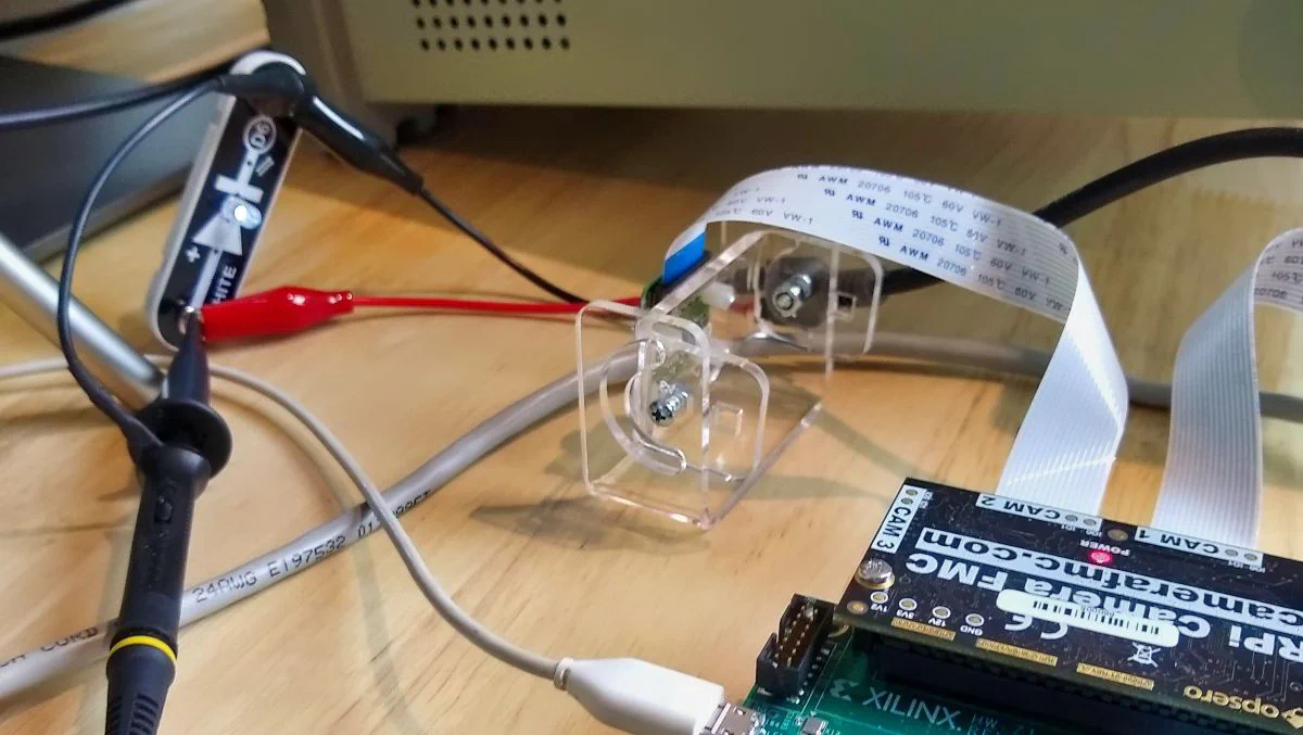
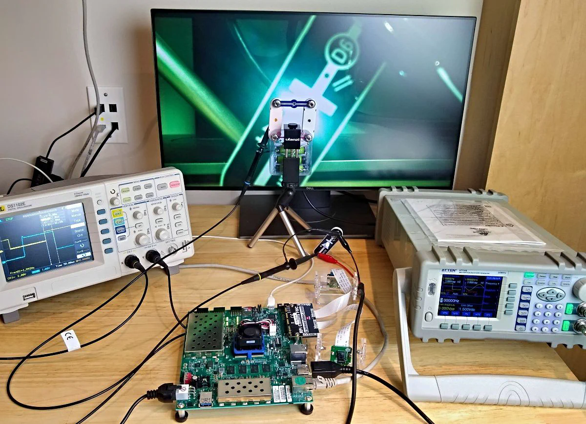
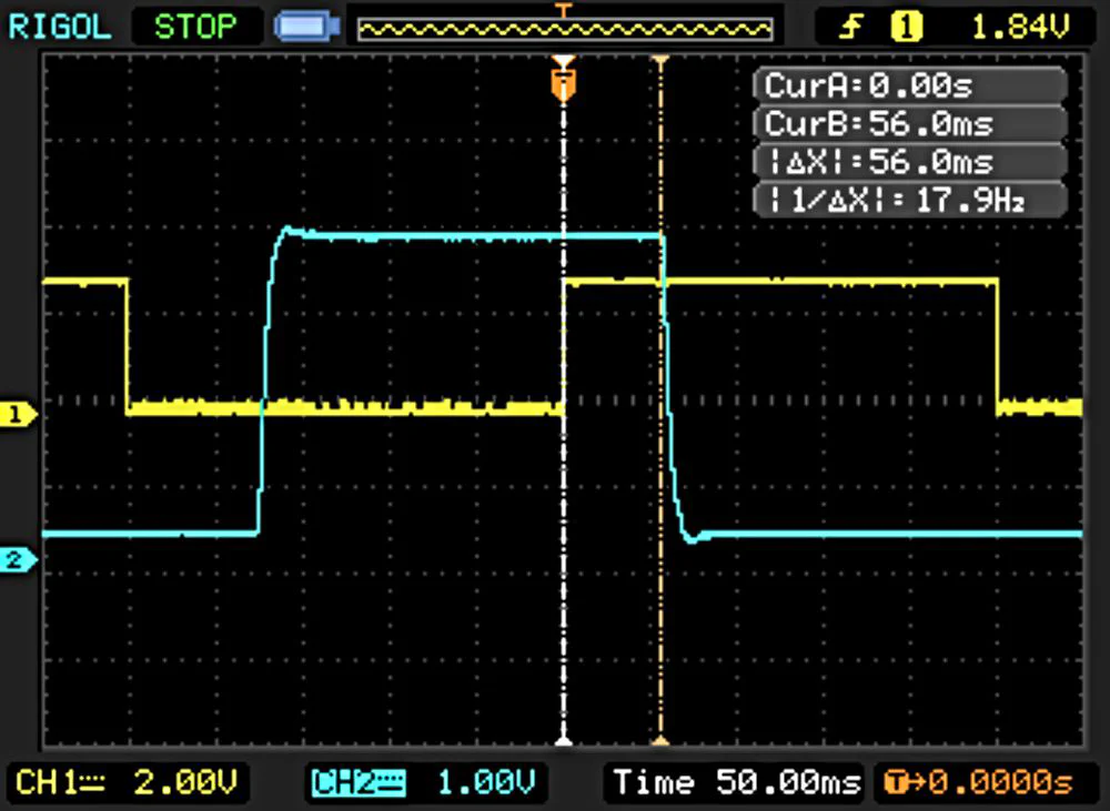
This is the more challenging part. To measure the glass-to-glass latency, I’ve setup an LED in front of the camera and a photodiode in front of the monitor. A signal generator drives the LED and also channel 1 of an oscilloscope. The output of the photodiode is connected to channel 2 of the oscilloscope. The latency is measured as the time lag between the input pulse and the output pulse. Here’s a list of my test equipment:
The image below shows the entire setup.
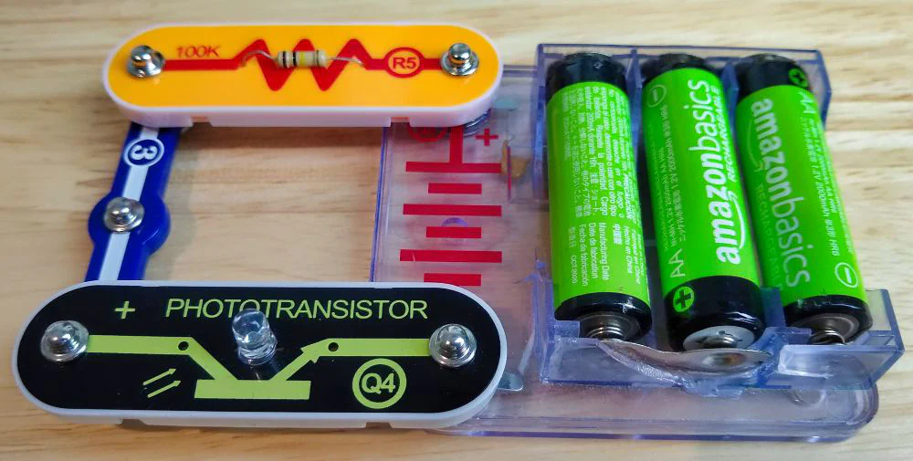
The detector below, made up of parts from my son’s Snap circuits kit is just a photodiode, a 100K resistor and a battery. The oscilloscope probe is connected across the photodiode, consequently the signal that we observe goes LOW when light shines on the photodiode, and it goes HIGH when in the dark. Note that the LED drive signal does the opposite, it is HIGH when the LED is ON, and LOW when the LED is OFF. It is important to keep this in mind when measuring the lag.
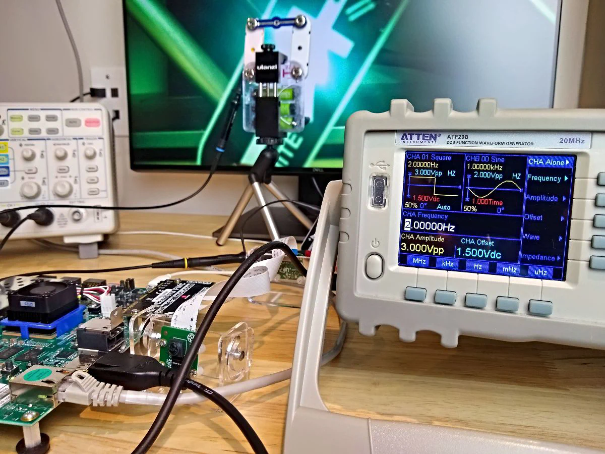
The signal generator shown below, drives the LED with pulses that we also observe on the oscilloscope. Here I’m driving the LED with a square wave of 3VDC peak-to-peak, offset of 1.5V, a 50% duty cycle at a frequency of 2Hz.
Admittedly, taking the actual measurements was a bit tedious, I basically used the oscilloscope vertical cursors to measure the time between input and output pulses. I made 10+ measurements and recorded the minimum and maximum values. The screenshot below is from testing the standalone application. The signal gets a lot more messy when you test the NLP-SmartVision app because the auto-gain/exposure control comes into play and I haven’t figured out how to disable it. In the end, I used the core of a toilet paper roll to block out light from the rest of the monitor and keep the detector focused on the LED.
We gained some interesting insights from this comparison of the performance of operating systems and camera types for an FPGA based AI Vision application, but it also raised some new questions:
I hope to provide answers to these questions in a future post and provide even more detailed insights to how you can optimize the performance of these FPGA-based AI Vision systems. Have a great week!