Title here
Summary here


Zero-copy recording from the FPGA fabric to NVMe SSDs, and playback back into it
October 13, 202615 minutes

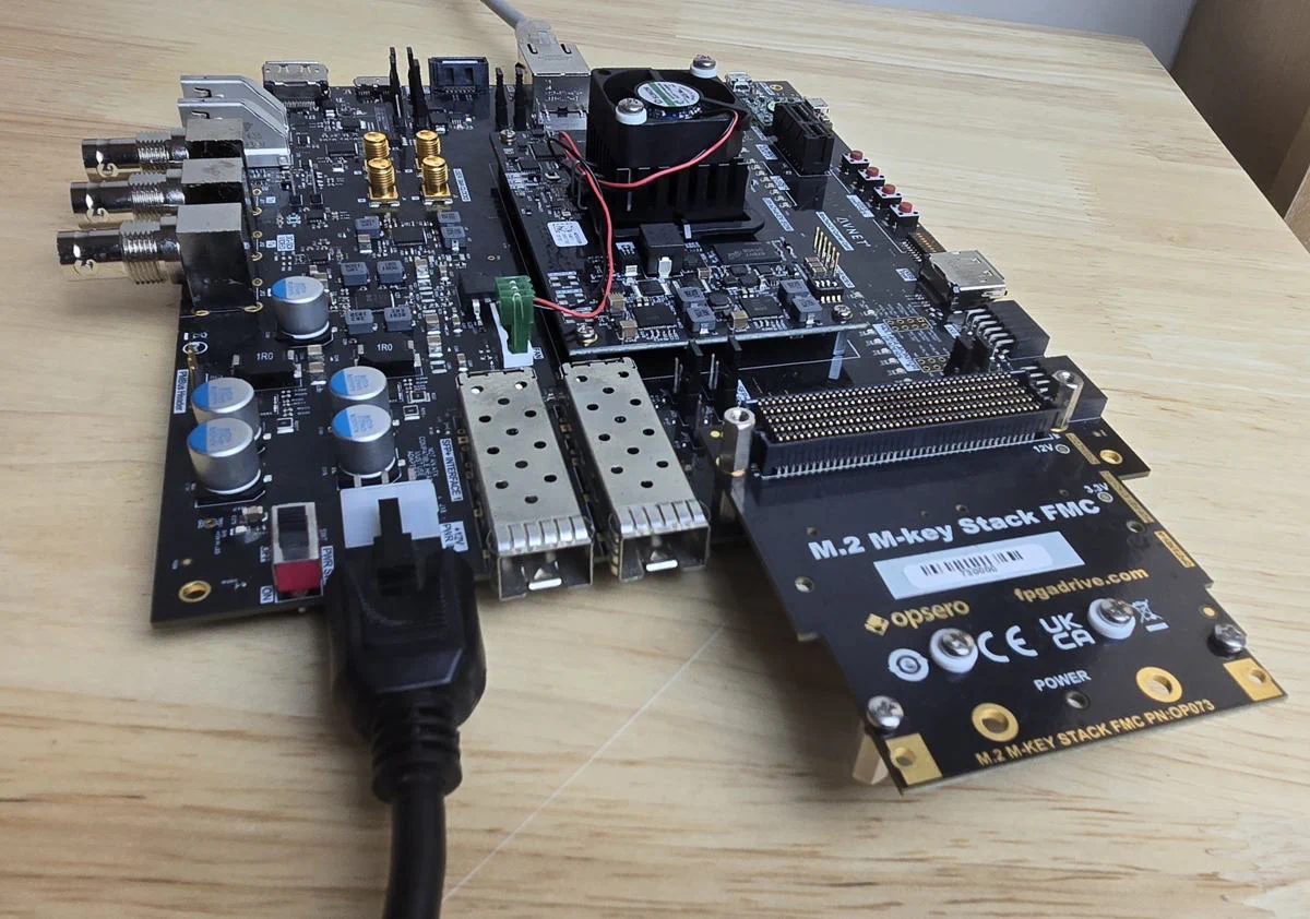
In this post I’m going to introduce our new reference design, the FPGA Drive Recorder. It records a data stream generated in the FPGA fabric to a file on one or two NVMe SSDs, and it can play those recordings back into the fabric. The SSDs connect to the FPGA through our FPGA Drive FMC Gen4 (OP063) or M.2 M-key Stack FMC (OP073), and the design runs embedded Linux built with the AMD Yocto / Embedded Development Framework (EDF) 2025.2.
Over the years, a lot of customers have asked me for something like this. Our fpga-drive-aximm-pcie reference design gets the SSDs working as Linux block devices, but it doesn’t get your data from the fabric onto them, and I never had a working design that I could hand over for that. Almost two years ago, at the end of the Versal PL NVMe SSD speed test post, I wrote that I wanted to build something closer to a real application: generate samples in the PL, store them on the SSD, and validate the data. This is that design, and I’m really happy to finally deliver it.
This post covers what the design does, where the line sits between the FPGA and Linux, the performance we measured, and some use cases. For the fine detail (register map, driver, file format, full benchmark tables) see the user guide.
Linux runs on the processor of the target board, and it owns the SSDs and the filesystem. The recording is zero-copy:
fdrec kernel driver pins for the DMA (the default ring is 32 x 8 MB).O_DIRECT write, and the NVMe
controller of the SSD reads the data straight out of that same buffer.The data source is a block-design hierarchy called user_data_source with a 128-bit
AXI4-Stream output. In the reference design it holds a test pattern generator that models an
ADC: it produces data at a programmable rate and it cannot be stalled. That’s the point
where you drop in your own ADC, sensor or processing logic. If the SSDs can’t keep up, the data
that doesn’t fit is dropped and counted in the fabric. It’s never silently lost: every
recording reports its drop count in the file header, and a valid recording has a drop count of
zero. The fdverify tool then checks a test-pattern recording beat by beat.
Playback is the same path in reverse. The app reads a recording into the hugepage buffers with
O_DIRECT reads, and the DMA streams them into a second hierarchy, user_data_sink. In the
reference design that’s a hardware checker that consumes the stream at a programmable rate,
like a DAC would, and verifies every beat. You can replace it with your own logic too.
The image below shows the Zynq UltraScale+ version of the design.
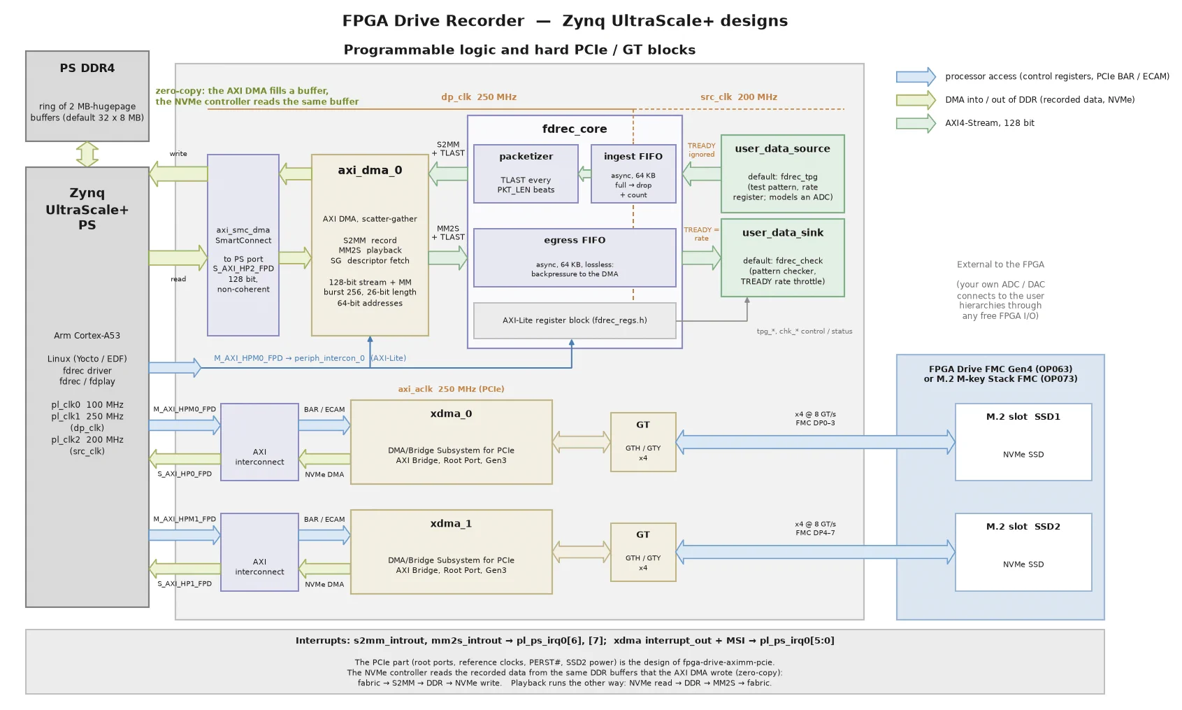
The PCIe part of the design (one PCIe Root Port per M.2 slot) is the design of
fpga-drive-aximm-pcie. The recorder adds the data source and sink, the fdrec_core FIFOs
and registers, and the AXI DMA. The datapath is 128 bits wide at 250 MHz (dp_clk) on the DMA
side, which is 4 GB/s, and the source and sink run at 200 MHz (src_clk), so the test pattern
generator tops out at 3.2 GB/s. The Versal version uses exactly the same datapath; only the
platform around it changes (CIPS, the NoC and QDMA Root Ports).
The Linux image comes with these tools:
| Tool | What it does |
|---|---|
fdsetup-raid0.sh | Prepares the recording filesystem: one SSD, or a RAID0 array of two |
fdrec | Records the fabric stream to a file (zero-copy, io_uring + O_DIRECT) |
fdplay | Plays a recording back into the fabric |
fdverify | Verifies a test-pattern recording beat by beat |
fdbench.sh | Sweeps the generator rate to find the sustained recording rate of your SSDs |
Recordings are ordinary files: a 4096-byte header (with the start and stop times and the drop count) followed by the raw 16-byte beats (see the file format).
I want to be clear about this up front: this design does not implement complete NVMe offload. It is not an NVMe host engine in the fabric. Here is where the line sits:
fdrec driver manages the DMA
descriptors and the cache maintenance.The diagram below, from the user guide, shows who touches each buffer and when.

Keeping Linux in charge has real advantages: recordings are normal files, you can use RAID0,
fio, nvme-cli and every other Linux tool, and the design needs no paid IP. The trade-off is
that you need a running Linux system, and the rate you can sustain is set by the SSDs and by
the Linux I/O path.
If you need CPU-less operation, or rates beyond what Linux can sustain, then you need the NVMe host in hardware. Opsero is partnered with Missing Link Electronics (MLE), and their NVMe Streamer IP core does complete NVMe offload: the NVMe protocol is handled in the fabric rather than by a processor running Linux. The FPGA Drive Recorder is a free, open-source starting point for the many applications that fit within what Linux can do, and NVMe Streamer is for the ones that don’t.
All of these figures were measured on hardware on 2-3 October 2026 with two SSDs, a Samsung 970 EVO 250GB and a Samsung 950 PRO 256GB, both linked at PCIe Gen3 x4, used alone and as a RAID0 pair (512 KB chunks, XFS). The boards were the UltraZed-EV Carrier (four Cortex-A53 cores at 1.1 GHz), the AMD ZCU106 (four Cortex-A53 cores at 1.2 GHz) and the AMD VCK190 (two Cortex-A72 cores at 1.4 GHz). The benchmarks page has every measurement and the method.
The pass criterion is stricter than a typical SSD benchmark: a recording rate passes only
if fdrec drops zero beats over the whole recording and fdverify reports a clean file. The
source can’t be stalled, so a pass means the whole chain (DMA, driver, filesystem, SSD) kept up
from the first byte to the last. Playback is clean when the hardware checker sees no
underflows and no errors.
Here’s how the recorder’s results compare to what Samsung claims for these drives. “Burst” is
the highest clean rate for a 4000 MiB recording, which fits inside the 970 EVO’s SLC write
cache. “Sustained” is the highest clean rate for a 32 GB recording, found with fdbench.sh in
250 MB/s steps. Playback is the highest clean fdplay rate for 4000 MiB (that sweep stops at
3000, the last step below the 3.2 GB/s sink maximum). All figures are in MB/s.
| SSD | Rated write | Recorder burst | Recorder sustained (32 GB) | Rated read | Playback (UltraZed-EV / ZCU106 / VCK190) |
|---|---|---|---|---|---|
| Samsung 970 EVO 250GB | 1500 (300 after the TurboWrite cache) | 1500 | 250 | 3400 | 1500 / 1500 / 3000 |
| Samsung 950 PRO 256GB | 900 | 750-1000 | 750 | 2200 | 1500 / 1500 / 2250 |
| RAID0 of both | - | 1750-2000 | 500 | - | 2750 / 3000 / 3000 |
A few things jump out:
The docs have a whole section on where the bottlenecks are, but here’s the short version, in the order the limits usually bite.
1. The SSD’s SLC cache. Most consumer SSDs write into a fast pseudo-SLC cache first and move the data to the slower TLC flash later. While the cache lasts, the drive writes at its datasheet rate; once it’s full, the rate drops. The 970 EVO 250GB writes at up to ~1.5 GB/s for about 13-14 GB on an empty, trimmed drive, then at about 330 MB/s. Samsung is upfront about this (300 MB/s after TurboWrite), but it’s easy to miss. A recorder writes at a constant rate for as long as the recording lasts, so the post-cache rate is the one that counts. The 950 PRO has no comparable cliff, which is why its sustained rate is so much closer to its burst rate.
2. The drive’s worst moment, not its average. A recording passes only if no beat is dropped
over its whole length, so the rate is set by the drive’s slowest stretch: garbage collection,
the cache running out, a write-latency spike. That’s why the sustained recording rates are
below every average throughput figure on the benchmarks page, fio included. If you test a
drive with a short dd or fio run, you’re measuring its cache and overstating what it can
sustain.
3. The Linux I/O path and the CPU. Even without a data copy, every write goes through the
filesystem, the block layer and the NVMe driver, and that costs CPU time. On the UltraZed-EV,
fdrec uses about 2.5-3 % of one 1.1 GHz Cortex-A53 core per 100 MB/s, almost all of it system
time. That’s about half the CPU of a dd write, which has to produce every byte and runs one
request at a time. Reads are where the host really shows: on the Zynq UltraScale+ boards the
read path limits playback to roughly 1.3-1.6 GB/s per drive, while the VCK190’s Cortex-A72
cores read the same drives close to or above their ratings with fio (3217 MB/s from the 970 EVO).
4. NVMe queues and RAID0. On every board we tried, the Linux NVMe driver set up the 970 EVO 250GB with a single I/O queue (the 950 PRO got two to four), so all of its completions are handled by one core. RAID0 stripes every chunk across both drives in turn, so the array runs at twice the slower drive’s rate. With the 970 EVO in the pair, that’s why the RAID0 sustains 500 MB/s: twice the 970 EVO’s 250 MB/s.
What is not the bottleneck at these rates: the PCIe link (Gen3 x4 carries about 3.3 GB/s of payload, Gen4 x4 about 6.5 GB/s), the PS DDR, and the fabric datapath (4 GB/s). I speculated about the PCIe link in earlier posts, so it’s nice to have that settled with data.
To get more, use drives designed for sustained writes (enterprise or industrial, MLC or SLC flash, or larger capacities with a bigger cache), RAID0 of two identical drives, and SSDs that expose several NVMe I/O queues. Also watch the heat: many SSDs throttle when they get hot during long recordings.
Even the most conservative figure, 250 MB/s sustained with a budget consumer drive, opens up a lot of applications, and the better drive or a RAID0 pair raises that to 500-750 MB/s:
user_data_sink can be fed at 1.5 GB/s from a single drive on Zynq UltraScale+,
and at up to 3.2 GB/s from a RAID0 pair on the VCK190.At the time of writing, the design supports these target boards:
| Target board | Target design | FMC connector | M.2 slots (PCIe lanes) | Vivado edition |
|---|---|---|---|---|
| UltraZed-EV Carrier | uzev | HPC | 2x Gen3 x4 | Standard (free) |
| AMD Zynq UltraScale+ ZCU106 | zcu106_hpc0 | HPC0 | 2x Gen3 x4 | Standard (free) |
| AMD Versal AI Core VCK190 | vck190_fmcp1 | FMCP1 | 2x Gen4 x4 | Enterprise |
The VCK190 needs a Vivado Enterprise license because the XCVC1902 device isn’t supported by the free Standard Edition. That’s a device license; no design needs an IP license. More Linux-capable Zynq UltraScale+ and Versal targets of fpga-drive-aximm-pcie are being added.
sdtgen/xsct for the Yocto flow)There’s no PetaLinux flow (PetaLinux is being retired, see my Yocto/EDF migration post) and no bare-metal application. The recorder needs Linux.
Clone the repo (with its submodules) and build everything for your target. The example below is
for the UltraZed-EV; use zcu106_hpc0 or vck190_fmcp1 for the other boards. This builds the
Vivado project and XSA, then the Yocto image, and gathers the boot files into bootimages/:
git clone --recursive https://github.com/fpgadeveloper/fpga-drive-recorder.git
cd fpga-drive-recorder
./build.sh all --target uzev
Flash Yocto/uzev/images/linux/rootfs.wic.xz to the SD card, copy BOOT.BIN onto its first
(FAT) partition, and boot the board with one or two SSDs on the mezzanine card. Log in as
amd-edf (you choose the password on the first login). Then:
# 1. Make a filesystem on the SSD(s) and mount it at /mnt/rec -- ERASES THE DRIVES.
#    Both M.2 slots populated: RAID0 across the two SSDs
sudo fdsetup-raid0.sh
#    or a single SSD:
sudo fdsetup-raid0.sh --single /dev/nvme0n1

# 2. Record 10 GB of the test pattern at 1 GB/s (exit code 0 = no dropped beats)
sudo fdrec --rate 1000MB --size 10G /mnt/rec/test.dat

# 3. Verify every beat of the recording
sudo fdverify /mnt/rec/test.dat

# 4. Play it back into the fabric, where the hardware checker consumes it at 1 GB/s
sudo fdplay --rate 1000MB /mnt/rec/test.dat

# Find the sustained recording rate of your SSD(s): 32 GB per step
sudo fdbench.sh
Run fdbench.sh with your own SSDs before you design around a rate. As the table above shows,
the drive matters far more than the board. The
test procedure in the user guide
shows the expected output of each step.
To record your own data, replace the test pattern generator in user_data_source (see
custom data source) and run
fdrec --no-tpg. Keep in mind the contract: the source is never stalled, the stream is 128 bits
wide, and the recorder adds no framing or timestamps to your data. If you need timestamps or
frame markers, put them into the stream in your source logic.
Here are a few applications that I think are a good fit for this design:
I’m currently using the FPGA Drive Recorder to build an Ethernet packet recorder. It’s a work in progress, but here’s the idea. The recorder taps a 1G Ethernet link and stores the packets directly to the NVMe drive, as a file that you can open in Wireshark. It’s all controlled through a web interface.
The hardware is an AMD ZCU106 with the FPGA Drive FMC Gen4 on HPC1 and the Ethernet FMC Max (OP080) on HPC0. The ZCU106’s on-board Ethernet port is used for the web interface, so the control traffic never shares a port with the link being tapped.
Because every packet is timestamped as it’s captured, the recorder can also do the reverse: it can replay Ethernet traffic that was recorded earlier, with the exact original timing. That maps nicely onto the two halves of this design, with the capture logic as the data source and the replay logic as the data sink. I see a lot of uses for that in testing network equipment: record a problem once, then reproduce it on the bench as many times as you need.
I’ll write more about it when it’s ready.
The FPGA Drive Recorder gives you a free, open-source, zero-copy path from the FPGA fabric to a file on an NVMe SSD and back, with Linux in charge of the drives. It’s not a hardware NVMe host, and it doesn’t try to be one. If you need complete NVMe offload, look at MLE’s NVMe Streamer. But for a lot of applications, the rates that Linux and a good SSD can sustain are plenty.
If you build something with it, test it with SSDs that aren’t on our list, or get it working on another board, I’d really like to hear about it. And if you have any questions, feel free to reach out.