Tutorial Overview
In this example, we will develop a simple FPGA project using the Base System Builder that includes three peripherals: the RS232 UART and two GPIOs. One GPIO will be used for the DIP switches and the other for the LEDs. We will then use a C program to read data from the switches and write it to the LEDs. The result is that the LEDs will display the DIP switch settings.
This tutorial contains screenshots to guide you through the entire implementation process. Click on the images to view a higher resolution.
What you will learn
By following this example, you will learn:
- How to create an EDK project with the Base System Builder
- How to add a software application to an EDK project
- How to implement and test your design
Requirements
Before following this tutorial, you will need to do the following:
- Buy an ML505/ML506/ML507 or XUPV5 board if you don’t already have one. Xilinx supplies the ML50x boards, but the best deal is the XUPV5 from Digilent. Click the Digilent link for more information.
Create the Basic Project
Follow these steps to create the basic project:
- Open XPS. From the dialog box, select “Base System Builder wizard” and OK.
- You will be asked to specify which folder to place the project. Click “Browse” and create a new folder for the project. Click “OK”.
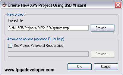
- We are given the choice to create a new project or to create one using the template of another project. Tick “I would like to create a new design” and click “Next”.
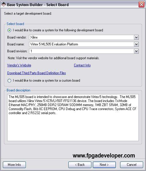
- On the “Select Board” page, select “Xilinx” as the board vendor. Then select the board you are using (eg. “Virtex 5 ML505 Evaluation Platform”). Select “1” as the board revision. Click “Next”. (Note: If you are using the XUPV5 (ML509) board, you might find that it is not listed. Select “Virtex 5 ML505 Evaluation Platform” instead.)
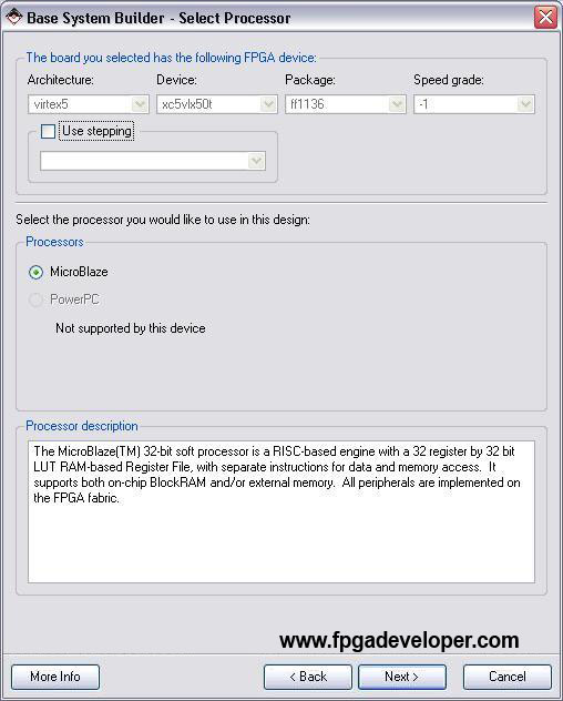
- On the “Select Processor” page, we normally have a choice between using the PowerPC “hard” processor, or the Microblaze “soft” processor. Since the Virtex-5 does not contain any PowerPCs, we can only select Microblaze. Click “Next”.
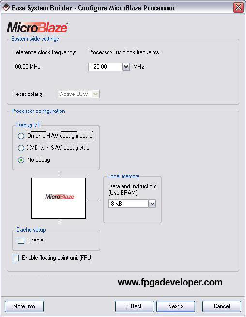
- On the “Configure Microblaze” page, select the clock frequency to be 125MHz. We will use the RS232 port for debugging rather than the JTAG, so select “No debug”. Click “Next”.
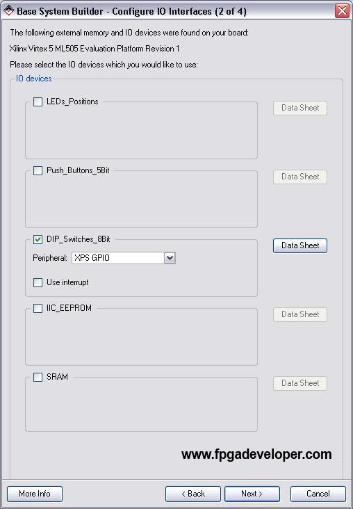
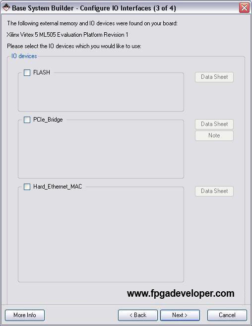
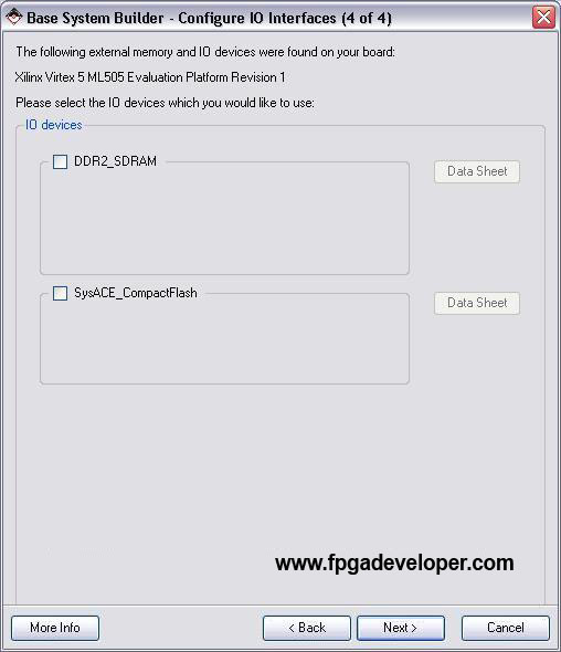
- In selecting the Additional IO Interfaces, leave
RS232_Uart_1,LEDs_8BitandDIP_Switches_8Bitticked and un-tick everything else.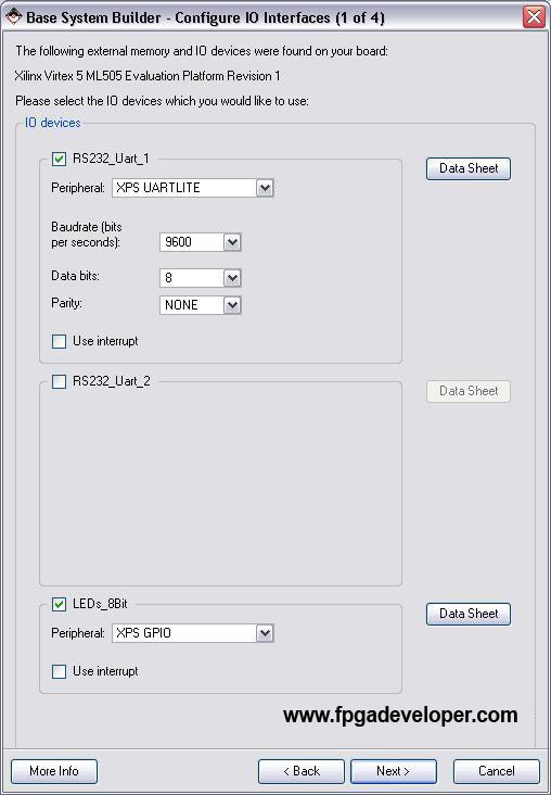
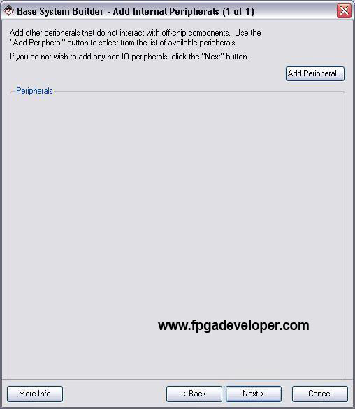
- On the “Add Internal Peripherals” page, click “Next”.
- On the “Software Setup” page, select
RS232_Uart_1for both STDIN and STDOUT. The Base System Builder can produce sample software applications to run on the Microblaze and test the memory and peripherals. For this project we will not need them as we will create our own. Un-tick “Memory Test” and “Peripheral Test”. Click “Next”.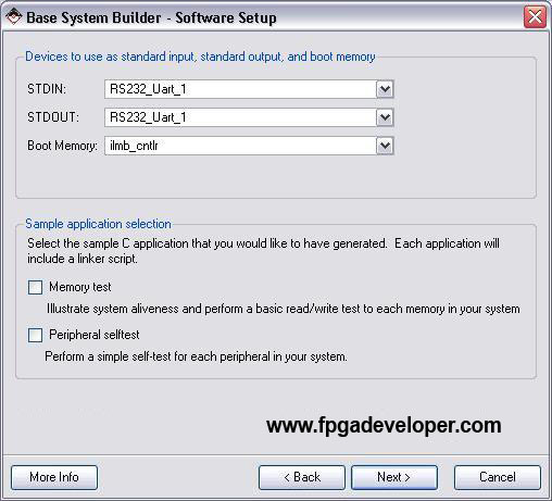
- Click “Generate”.
- Click “Finish”.
- If you are using the XUPV5 (ML509) board and you selected “Virtex 5 ML505 Evaluation Platform” in step 4 above, you must select the right Virtex-5 version in the project settings. Select “Project->Project Options” and set the Virtex-5 version to “XC5VLX110T”, package “FFG1136” and speed grade “-1”.


Create a Simple Application
Now that the basic project is made, we can create a simple software application to run on the Microblaze to test the DIP switches and LEDs.
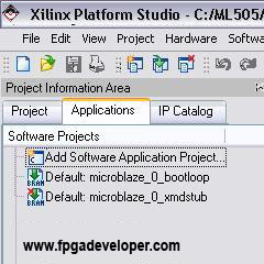
- Select the Applications tab. You will see a software application already there called
Default: microblaze_0_bootloop. The purpose of this application is to occupy the Microblaze in the case that there is no other software application in the design. It simply keeps the Microblaze running in an endless loop. - Double click “Add Software Application”.
- For the project name type “TestApp”. For the processor select
microblaze_0. Click “OK”.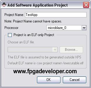
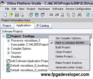
- From the Applications tab, right click on the software application
Default: microblaze_0_bootloopand select “Mark to Initialize BRAMs”. The icon will now have a small red cross signifying that it will not run on the Microblaze. - Right click on the software application we just created “Project: TestApp” and select “Mark to Initialize BRAMs”. The red cross on the icon of our software application should have been removed signifying that it will run on the Microblaze.
- From the menu select File->New, then select “Text file”. Copy the following code into the new file. Save the file as
TestApp.cin a folder called “TestApp” within the project folder.


#include "xparameters.h"
#include "xbasic_types.h"
#include "xgpio.h"
#include "xstatus.h"

XGpio GpioOutput;
XGpio GpioInput;

int main (void) {

  Xuint32 status;
  Xuint32 DataRead;
  Xuint32 OldData;

  // Clear the screen
  xil_printf("%c[2J",27);

  // Initialize the GPIO driver so that it's ready to use,
  status = XGpio_Initialize(&GpioOutput,
                                 XPAR_LEDS_8BIT_DEVICE_ID);
  if (status != XST_SUCCESS)
    return XST_FAILURE;
  // Set the direction for all signals to be outputs
  XGpio_SetDataDirection(&GpioOutput, 1, 0x0);

  // Initialize the GPIO driver so that it's ready to use,
  status = XGpio_Initialize(&GpioInput,
                         XPAR_DIP_SWITCHES_8BIT_DEVICE_ID);
  if (status != XST_SUCCESS)
    return XST_FAILURE;
  // Set the direction for all signals to be inputs
  XGpio_SetDataDirection(&GpioInput, 1, 0xFFFFFFFF);

  OldData = 0xFFFFFFFF;
  while(1){
    // Read the state of the DIP switches
    DataRead = XGpio_DiscreteRead(&GpioInput, 1);

    // Send the data to the UART if the settings change
    if(DataRead != OldData){
      xil_printf("DIP Switch settings: 0x%X\r\n", DataRead);
      // Set the GPIO outputs to the DIP switch values
      XGpio_DiscreteWrite(&GpioOutput, 1, DataRead);
      // Record the DIP switch settings
      OldData = DataRead;
    }
  }
  return 0;
}
- In the “Project:TestApp” tree, right click on “Sources” and select “Add existing files”. Select the
TestApp.cfile that we just created and click “OK”.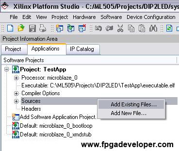
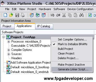
- Right click on the “Project: TestApp” application and select “Generate Linker Script” and click “Generate”.
- Select “Software->Generate Libraries and BSPs” from the menu.


Download and Test the Project
- Open a Hyperterminal window with the required settings. For the correct settings, see Hyperterminal Settings.
- Turn on the ML505 board.
- We can now download our hardware description and software application to the FPGA. From the XPS software, select “Device Configuration->Download Bitstream”.
The simple C program that we added to this project simply reads the DIP switch settings and sends a message with that data to the UART. It also writes the same values to the LEDs. When the application is running and Hyperterminal is open, the DIP switch settings should be seen on the LEDs and on the Hyperterminal screen. Change the DIP switches to see the message change.
After a few changes in the DIP switches, the Hyperterminal output should look similar to the screen shot below:

The project folder for this tutorial can be downloaded in a compressed ZIP file DIP2LED-EDK10-1.zip . Right-click on the link and select “Save Link As”.
In the next tutorial, Manually Add a Peripheral to a Project, we show how to manually add peripherals to a design, instead of letting the BSB do all the work.