Tutorial Overview
Sometimes we have an .ngc file from CORE Generator (or some other source) that we would like to bring into EDK as a peripheral. This project is a simple example of integrating a blackbox design into a peripheral generated by the Peripheral Wizard. We will first create a blackbox multiplier using the Xilinx CORE Generator and then we will use the generated .ngc file in our peripheral.

The multiplier will take in two 16 bit unsigned inputs and have a 32 bit unsigned output. A single 32 bit write to the peripheral will contain the two 16 bit inputs, separated by the lower and higher 16 bits. A single 32 bit read from the peripheral will contain the result from the multiplication of the two 16 bit inputs. Instead of registers, we will use a read and write FIFO for the interface with the software application. In this way, the peripheral write FIFO can be loaded with a number of multiplications to perform, and the results can be pushed into the read FIFO for the software application to retrieve at its convenience. Practically, this design does not serve much purpose, but it is a simple demonstration of integrating blackbox designs into peripherals.
This tutorial contains screenshots to guide you through the entire implementation process. Click on the images to view a higher resolution.
Requirements
Before following this tutorial, you will need to do the following:
- Buy an ML505/ML506/ML507 or XUPV5 board if you don’t already have one. Xilinx supplies the ML50x boards, but the best deal is the XUPV5 from Digilent. Click the Digilent link for more information.
Create the Basic Project
Follow these steps to create the basic project:
- Open XPS. From the dialog box, select “Base System Builder wizard” and OK.
- You will be asked to specify which folder to place the project. Click “Browse” and create a new folder for the project. Click “OK”.
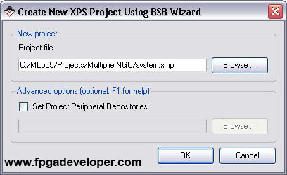
- We are given the choice to create a new project or to create one using the template of another project. Tick “I would like to create a new design” and click “Next”.
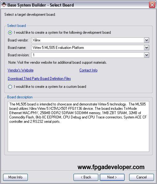
- On the “Select Board” page, select “Xilinx” as the board vendor. Then select the board you are using (eg. “Virtex 5 ML505 Evaluation Platform”). Select “1” as the board revision. Click “Next”. (Note: If you are using the XUPV5 (ML509) board, you might find that it is not listed. Select “Virtex 5 ML505 Evaluation Platform” instead.)
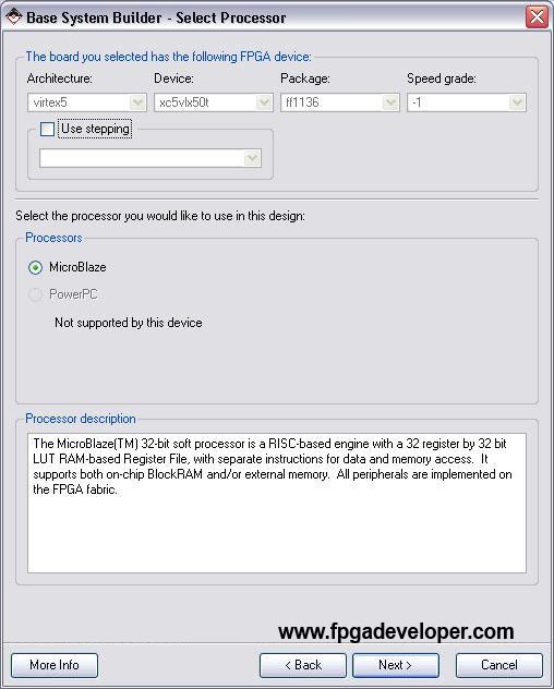
- On the “Select Processor” page, we normally have a choice between using the PowerPC “hard” processor, or the Microblaze “soft” processor. Since the Virtex-5 does not contain any PowerPCs, we can only select Microblaze. Click “Next”.
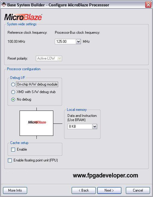
- On the “Configure Microblaze” page, select the clock frequency to be 125MHz. We will use the RS232 port for debugging rather than the JTAG, so select “No debug”. Click “Next”.
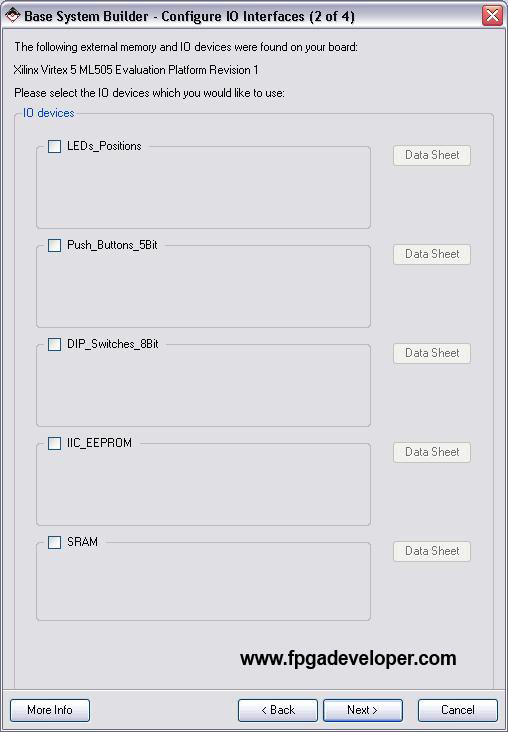
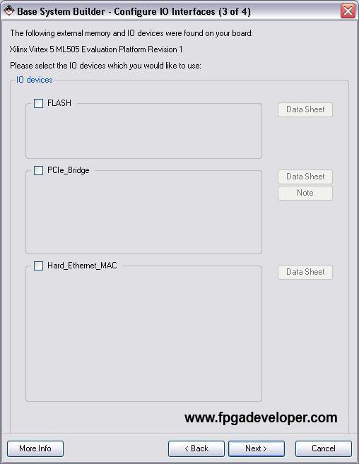
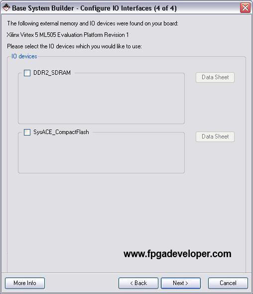
- In selecting the Additional IO Interfaces, leave
RS232_Uart_1ticked and un-tick everything else.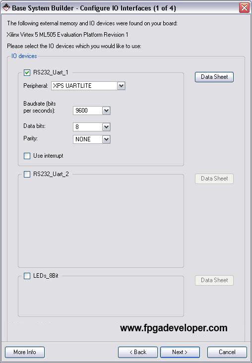
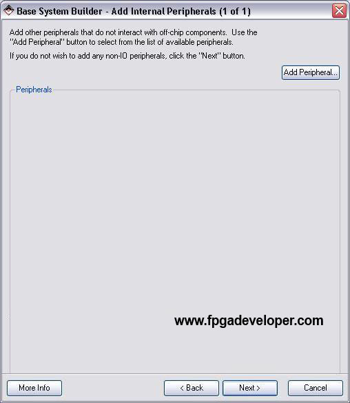
- On the “Add Internal Peripherals” page, click “Next”.
- On the “Software Setup” page, select
RS232_Uart_1for both STDIN and STDOUT. Un-tick “Memory Test” and leave “Peripheral Test” ticked. Click “Next”.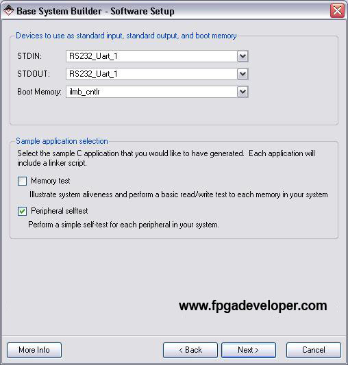
- Click “Generate”.
- Click “Finish”.
- If you are using the XUPV5 (ML509) board and you selected “Virtex 5 ML505 Evaluation Platform” in step 4 above, you must select the right Virtex-5 version in the project settings. Select “Project->Project Options” and set the Virtex-5 version to “XC5VLX110T”, package “FFG1136” and speed grade “-1”.


Create the Multiplier Peripheral
Follow these steps to create the multiplier peripheral.
- Select from the menu “Hardware->Create or Import Peripheral”. Click “Next”.
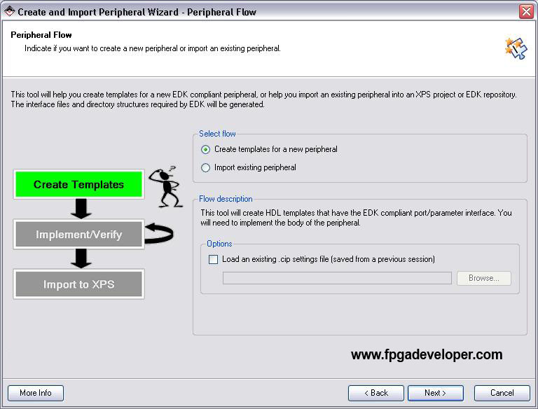
- Select “Create templates for a new peripheral” and click “Next”.
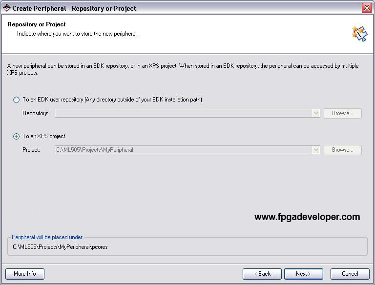
- We must now decide where to place the files for the peripheral. They can be placed within this project, or they can be made accessible to other projects. Select “To an XPS project”. Click “Next”.
- On the “Name and Version” page, type
my_multiplierfor the peripheral name. Click “Next”.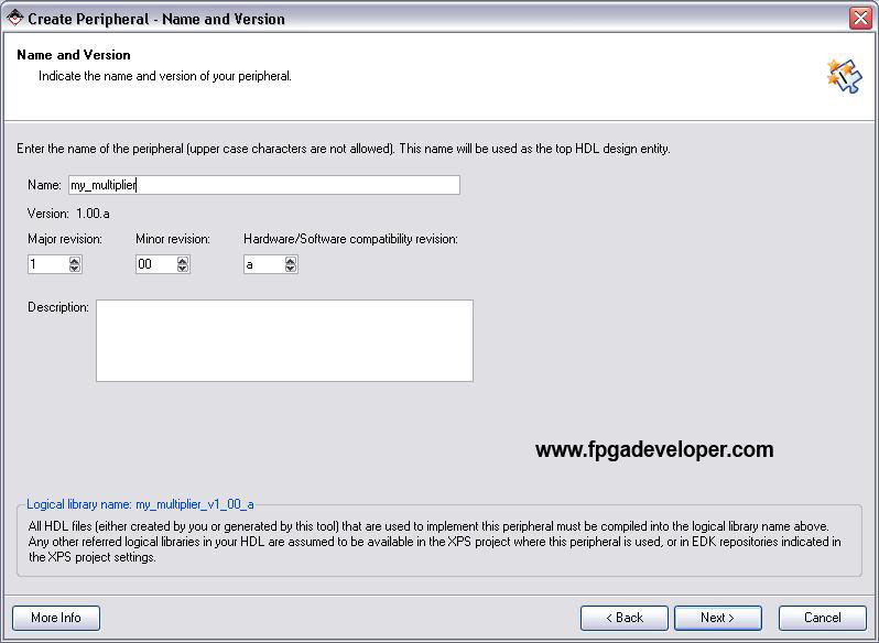
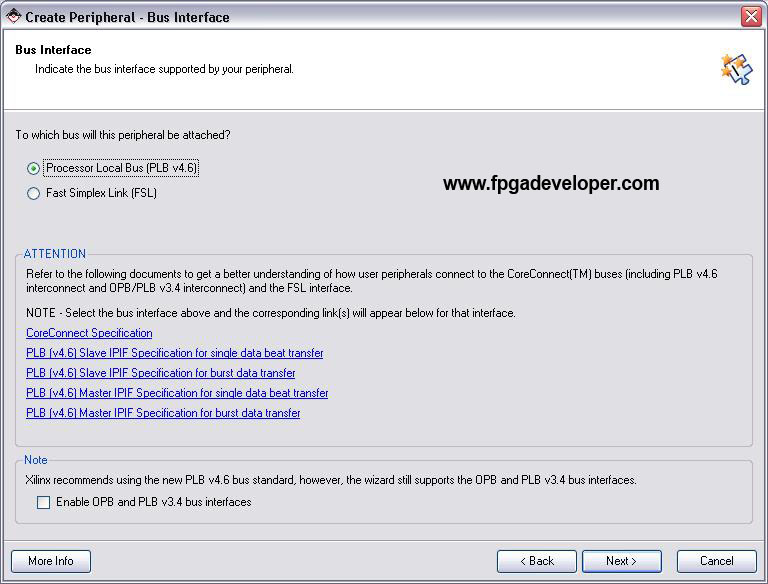
- On the “Bus Interface” page, select “Processor Local Bus” (PLB) and click “Next”.
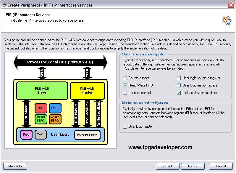
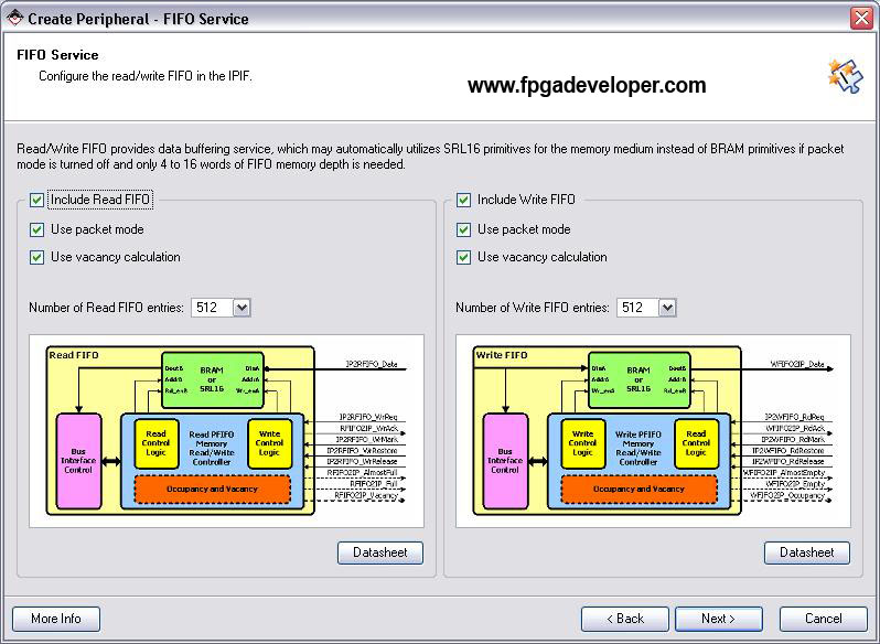
- On the “IPIF Services” page, we can make the Peripheral Wizard generate our VHDL template to include different features. Select “Read/Write FIFO” and “Include data phase timer”, un-tick everything else and click “Next”.
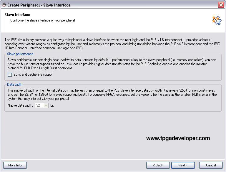
- On the “Slave Interface” page, click “Next”.
- For the FIFO Service settings, leave the defaults ticked: Include read FIFO, Include write FIFO, Use packet mode, Use vacancy calculation. Choose a FIFO depth of 512.
- On the “IP Interconnect” page we can customize our connection to the PLB but we will leave everything as is for simplicity. Click “Next”.
- On the “Peripheral Simulation Support” page, we can specify if we want the wizard to create a simulation platform for our peripheral. Click “Next” without ticking the option to generate.
- After the “Peripheral Implementation Support” page, the wizard will generate all the template files for us. Tick “Generate ISE and XST project files” and “Generate template driver files”. Click “Next”.
- Click “Finish”. Now our templates are created.


Create the Multiplier with CORE Generator
Follow these steps to generate the Multiplier.
- Leaving XPS running and your project open, from the “Start” menu, open Xilinx CORE Generator.
- Select “File->New Project”.
- Click “Browse” and select an appropriate location for a Coregen project. Within a Coregen project, you can create several cores that don’t necessarily relate to each other. Just select the folder where you normally place your projects, for example “C:\ML505\Projects”, and create a sub-folder called “Cores”. Open this folder and click “OK”.
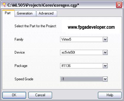
- You will be asked for the specifications of the FPGA you are using. All the cores you generate under this CORE Generator project file will be customized for the FPGA you specify here. Under the “Part” tab, select these options: Family “Virtex5”, Device “xc5vlx50t”, Package “ff1136”, Speed grade “-1”. Click “OK”. Note: If you are not using the ML505 board, these specifications may not apply to you. You will have to enter the details corresponding to the specific FPGA that you are using.
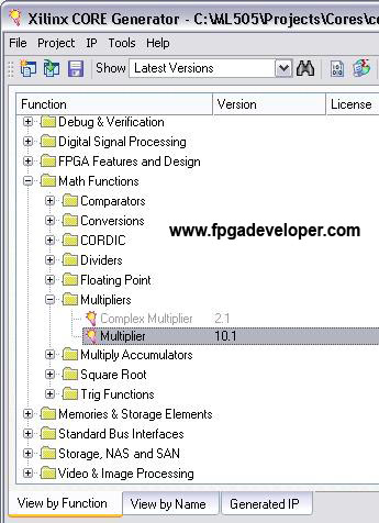
- When you have created your CORE Generator project, click on the “View by Function” tab to get a list of cores that you are able to generate.
- Open “Math Functions->Multipliers” and double-click on “Multiplier”.
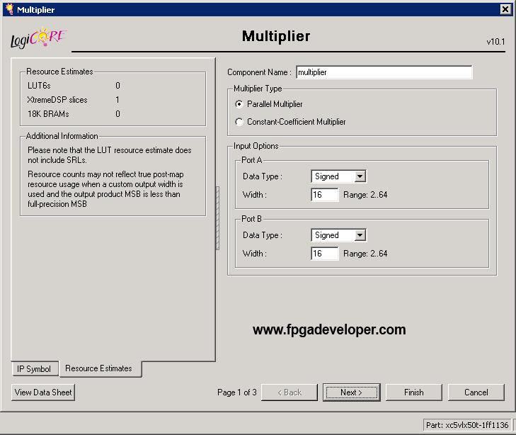
- A dialog box should open to allow you to select the features of the Multiplier you want. For “Multiplier Type” select “Parallel Multiplier”. Select “Signed” for both port inputs and give them a width of 16 bits. Click “Next”.
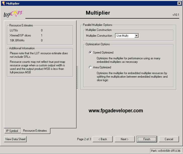
- For “Multiplier Construction” select “Use Mults”. In the “Optimization Options”, select “Speed Optimized”.
- Click “Finish”. Your Multiplier core will be generated and CORE Generator will display a list of all the generated files. Close this window, and close CORE Generator.


Modify the Peripheral
When we create a peripheral with read and write FIFOs, the Peripheral Wizard generates code in the user_logic.vhd file that loops the data from the write FIFO to the read FIFO. This makes it easy to test for the first time because one can write data to the peripheral and verify that it was received by reading back the same data. In our case, the loop-back design reduces the number of modifications we need to make because we want to do the same thing, only we want to first pass the data through the multiplier before putting it through to the read FIFO. Now we will add code in our peripheral template to instantiate a multiplier core and connect it to the read and write FIFOs.
- Select from the menu “File->Open” and look in the project folder.
- Open the folders:
pcores\my_multiplier_v1_00_a\hdl\vhdl. This folder contains two source files that describe our peripheralmy_multiplier.vhdanduser_logic.vhd. The first file is the main part of the peripheral and it implements the interface to the OPB. The second file is where we place our custom logic to make the peripheral do what we need it to do. This part is instantiated by the first file. - Open the file
user_logic.vhd. We will need to modify this source code to instantiate the multiplier and connect it to the read and write FIFOs. - Find the line of code that says
--USER signal declarations added hereand add the following lines of code just below.
component multiplier
  port (
    clk: IN std_logic;
    a: IN std_logic_VECTOR(15 downto 0);
    b: IN std_logic_VECTOR(15 downto 0);
    p: OUT std_logic_VECTOR(31 downto 0));
end component;
- Find the line of code that says
--USER logic implementation added hereand add the following lines of code just below.
multiplier_0 : multiplier
  port map (
    clk => Bus2IP_Clk,
    a => WFIFO2IP_Data(16 to 31),
    b => WFIFO2IP_Data(0 to 15),
    p => IP2RFIFO_Data);
- Find the line of code that says
IP2RFIFO_Data <= WFIFO2IP_Data;and comment it out (or delete it). Now, the read FIFO will be loaded with data from the multiplier. - Save and close the file.
Import the Peripheral
Now we will use the Peripheral Wizard again, but this time using the import function.
- Select from the menu “Hardware->Create or Import Peripheral” and click “Next”.
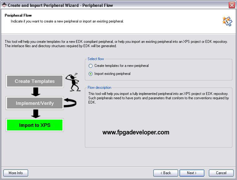
- Select “Import existing peripheral” and click “Next”.
- Select “To an XPS project”, ensure that the folder chosen is the project folder, and click “Next”.
- For the name of the peripheral, type
my_multiplier. Tick “Use version” and select the same version number that we originally created. Click “Next”. It will ask if we are willing to overwrite the existing peripheral and we should answer “Yes”.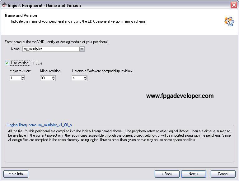
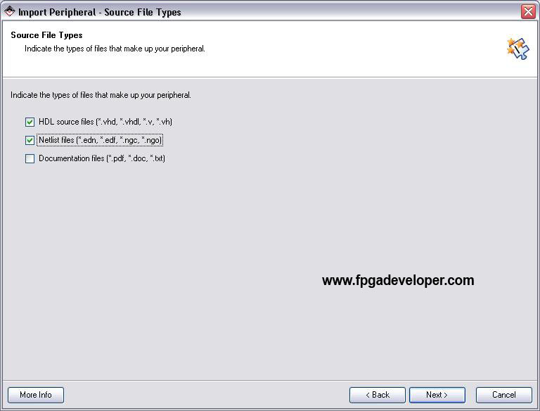
- Now we are asked about the files that make up our peripheral. As usual we tick “HDL source files” and in this case, to include our .ngc file, we will also tick “Netlist files”. Now click “Next”.
- Select “Use existing Peripheral Analysis Order file (*.pao)” and click “Browse”. From the project folder, go to
pcores\my_multiplier_v1_00_a\dataand select themy_multiplier_v2_1_0.paofile. Click “Next”.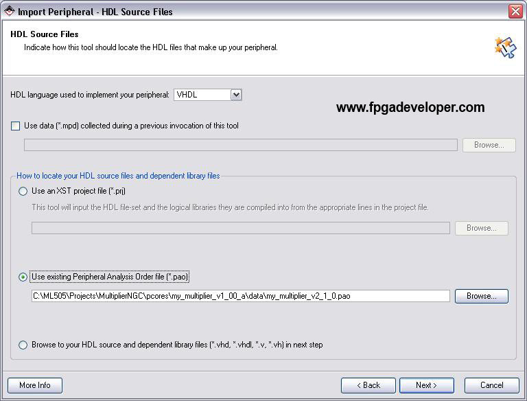
- On the HDL analysis information page, click “Next”. The wizard will mention if any errors are found in the design.
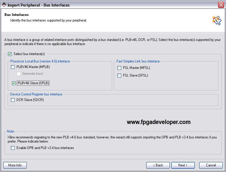
- On the Bus Interfaces page, tick “PLB Slave” and click “Next”.
- On the SPLB: Port page, click “Next”.
- On the SPLB: Parameter page, click “Next”.
- On the “Parameter Attributes” page, click “Next”.
- On the “Port Attributes” page, click “Next”.
- Now we should arrive at the “Netlist Files” page where we are asked to locate any netlist files or black-box components that are instantiated in our peripheral. Click “Select Files” and navigate your way to the CORE Generator project folder “Cores” that you created earlier. You will find a file called
multiplier.ngc. Select the file and click “Open”. The file should now be listed on the “Netlist Files” page. Click “Next”.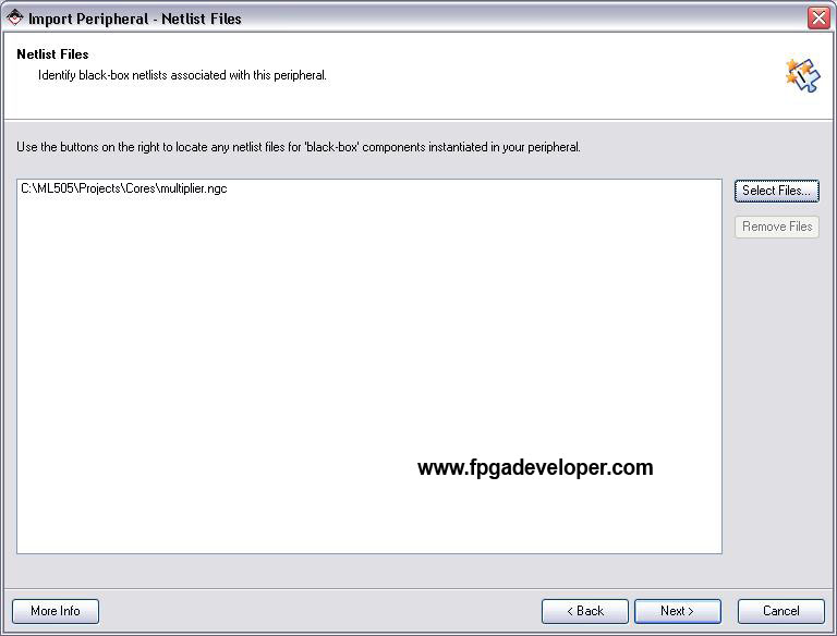
- Click “Finish”.


When you include .ngc files in a peripheral design as we just did, the Peripheral Wizard does some things behind-the-scenes that are important to know. Firstly, it makes a copy of the .ngc file and places it in the pcores\my_multiplier_v1_00_a\netlist folder (if that folder doesn’t exist, it creates one). Secondly, it creates a file called my_multiplier_v2_1_0.bbd in the pcores\my_multiplier_v1_00_a\data folder with the following contents:
############################################################
## Filename:          C:\ML505\Projects\MultiplierNGC\pcores-
/my_multiplier_v1_00_a/data/my_multiplier_v2_1_0.bbd
## Description:       Black Box Definition
## Date:              Mon Feb 11 16:53:42 2008 (by Create a-
nd Import Peripheral Wizard)
############################################################

Files
############################################################
multiplier.ngc
Finally, the Peripheral Wizard adds these two lines to the my_multiplier_v2_1_0.mpd file in the pcores\my_multiplier_v1_00_a\data folder:
OPTION STYLE = MIX
OPTION RUN_NGCBUILD = TRUE
The multiplier peripheral should now be accessible through the “IP Catalog->Project Local pcores” in the XPS interface.
Create an Instance of the Peripheral
Follow these steps to create an instance of the peripheral in the project.
- From the “IP Catalog” find the
my_multiplierIP core in the “Project Repository” group. Right click on the core and select “Add IP”.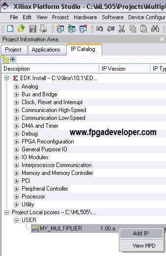
- From the “System Assembly View” using the “Bus Interface” filter, connect the
my_multiplier_0to the PLB bus.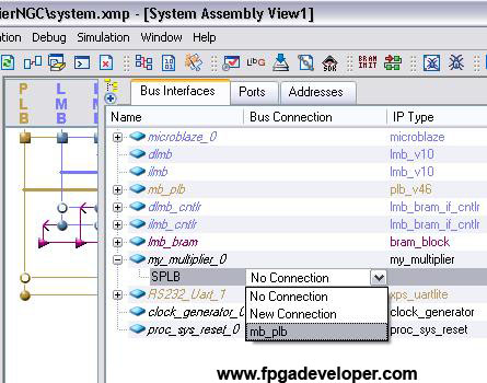
- Click on the “Addresses” filter. Change the “Size” for
my_multiplier_0to 64K. Then click “Generate Addresses”.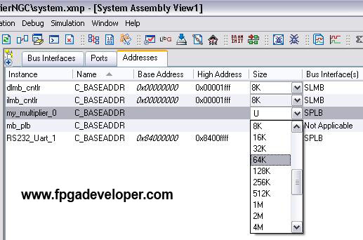


Now we have an instance of the multiplier peripheral in our project and our hardware design is complete.
Modify the Software Application
Now all we need to do is modify the software application to test our multiplier peripheral.
- From the “Applications” tab, open “Sources” within the “Project: TestApp_Peripheral” tree. Open the
TestApp_Peripheral.csource file. - Replace all the code in this file with the following source and save the file.
#include "xparameters.h"
#include "xbasic_types.h"
#include "xstatus.h"
#include "my_multiplier.h"

Xuint32 *baseaddr_p = (Xuint32 *)XPAR_MY_MULTIPLIER_0_BASEADDR;

int main (void) {
  Xuint32 i;
  Xuint32 temp;
  Xuint32 baseaddr;

  // Clear the screen
  xil_printf("%c[2J",27);

  // Check that the peripheral exists
  XASSERT_NONVOID(baseaddr_p != XNULL);
  baseaddr = (Xuint32) baseaddr_p;

  xil_printf("Multiplier Test\n\r");

  // Reset read and write packet FIFOs to initial state
  MY_MULTIPLIER_mResetWriteFIFO(baseaddr);
  MY_MULTIPLIER_mResetReadFIFO(baseaddr);

  // Push data to write packet FIFO
  for(i = 1; i <= 4; i++ ){
    temp = (i << 16) + i;
    xil_printf("Wrote: 0x%08x \n\r", temp);
    MY_MULTIPLIER_mWriteToFIFO(baseaddr,0, temp);
  }

  // pop data out from read packet FIFO
  for(i = 0; i < 4; i++){
    temp = MY_MULTIPLIER_mReadFromFIFO(baseaddr,0);
    xil_printf("Read:  0x%08x \n\r", temp);
  }

  // Reset the read and write FIFOs
  MY_MULTIPLIER_mResetWriteFIFO(baseaddr);
  MY_MULTIPLIER_mResetReadFIFO(baseaddr);

  xil_printf("End of test\n\n\r");

  // Stay in an infinite loop
  while(1){
  }
}
- Save and close the file.
Download and Test the Project
- Open a Hyperterminal window with the required settings. For the correct settings, see Hyperterminal Settings.
- Turn on the ML505 board.
- From the XPS software, select “Device Configuration->Download Bitstream”.
The Hyperterminal output should look as shown in the image below:

Remember, those numbers are in hexadecimal so 0x10 = 16!
The project folder for this tutorial can be downloaded in a compressed ZIP file MultiplierNGC-EDK10-1.zip . Right-click on the link and select “Save Link As”.
In the next tutorial, Integrating a VHDL Design into a Peripheral, we show how to integrate a custom VHDL design into the Peripheral Wizard templates.