Title here
Summary here
Tutorial on creating a custom AXI IP block in Vivado with integrated VHDL code on the MicroZed.
August 4, 20148 minutes

Update 2017-11-01: Here’s a newer tutorial on creating a custom IP with AXI-Streaming interfaces
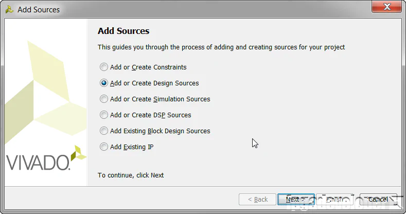
In this tutorial we’ll create a custom AXI IP block in Vivado and modify its functionality by integrating custom VHDL code. We’ll be using the Zynq SoC and the MicroZed as a hardware platform. For simplicity, our custom IP will be a multiplier which our processor will be able to access through register reads and writes over an AXI bus.
The multiplier takes in two 16 bit unsigned inputs and outputs one 32 bit unsigned output. A single 32 bit write to the IP will contain the two 16 bit inputs, separated by the lower and higher 16 bits. A single 32 bit read from the peripheral will contain the result from the multiplication of the two 16 bit inputs. The design doesn’t serve much purpose, but it is a good example of integrating your own code into an AXI IP block.
Before following this tutorial, you will need to do the following:
You can do this tutorial with any existing Vivado project, but I’ll start with the base system project for the MicroZed that you can access here:
Base system project for the MicroZed
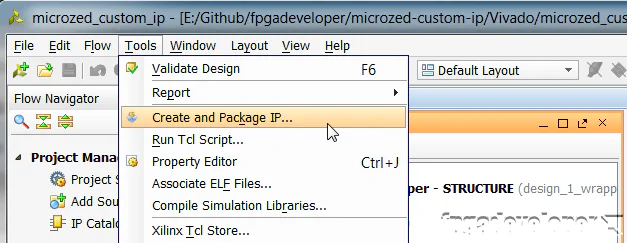
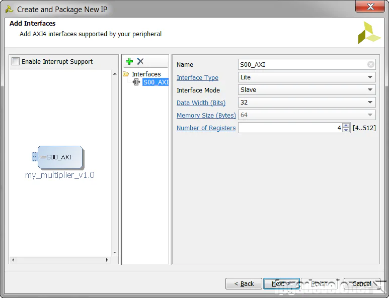
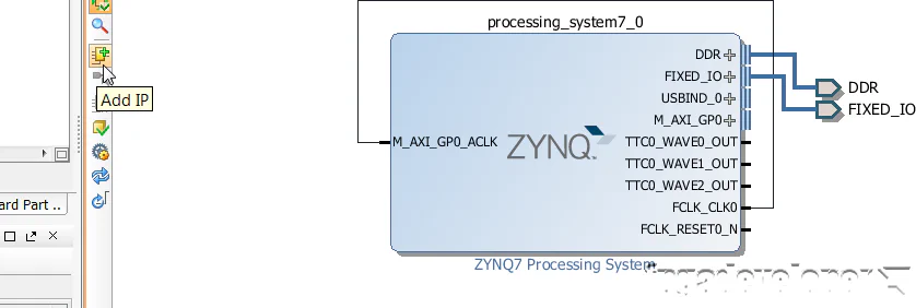
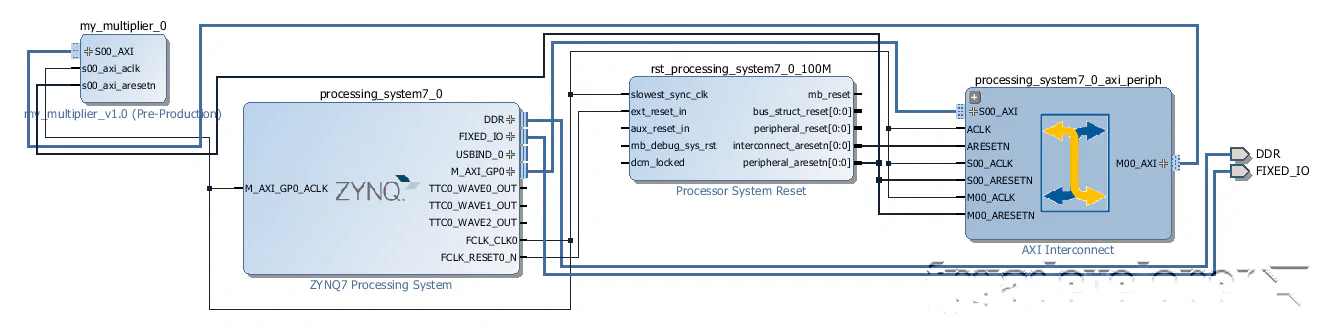
At this point, the peripheral that has been generated by Vivado is an AXI lite slave that contains 4 x 32 bit read/write registers. We want to add our multiplier code to the IP and modify it so that one of the registers connects to the multiplier inputs and another to the multiplier output.
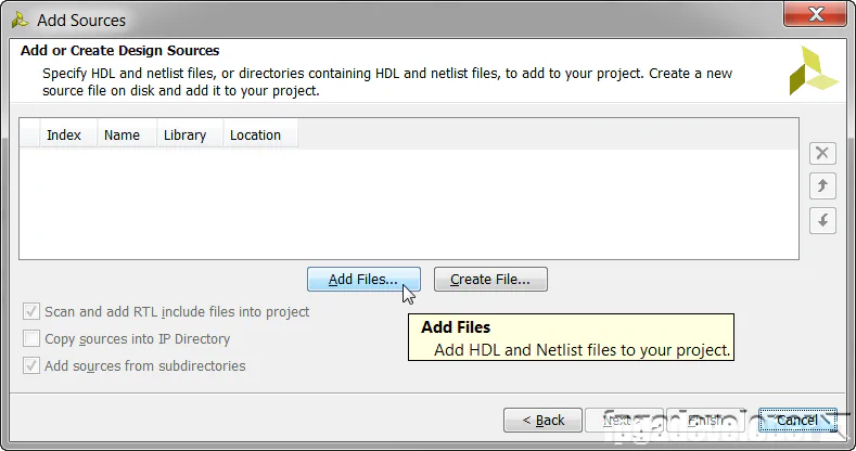
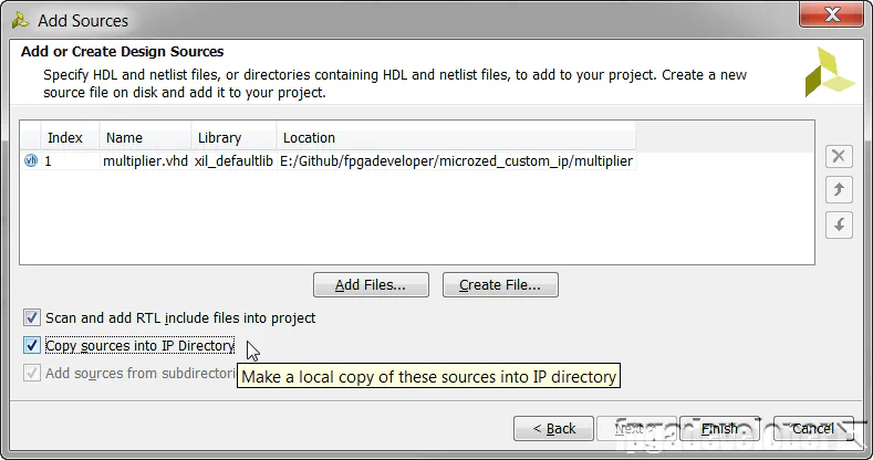
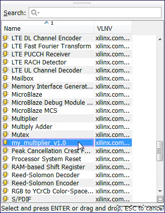
You can find the multiplier code on Github at the link below. Download the “multiplier.vhd” file and save it somewhere, the location is not important for now.
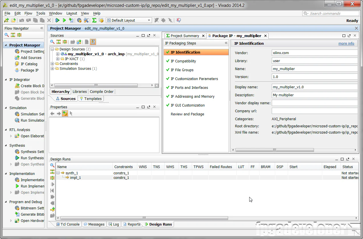
Note that these steps must be done in the Vivado window that contains the peripheral we just created (not the base project).
The multiplier code is now added to the peripheral, however we still have to instantiate it and connect it to the registers.
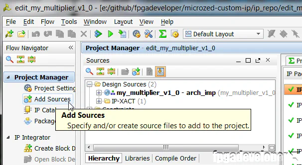
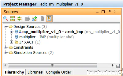
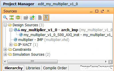
At this point, your Project Manager Sources window should look like the following:
signal multiplier_out : std_logic_vector(31 downto 0);

component multiplier
port (
  clk: in std_logic;
  a: in std_logic_VECTOR(15 downto 0);
  b: in std_logic_VECTOR(15 downto 0);
  p: out std_logic_VECTOR(31 downto 0));
end component;multiplier_0 : multiplier
port map (
clk => S_AXI_ACLK,
a => slv_reg0(31 downto 16),
b => slv_reg0(15 downto 0),
p => multiplier_out);
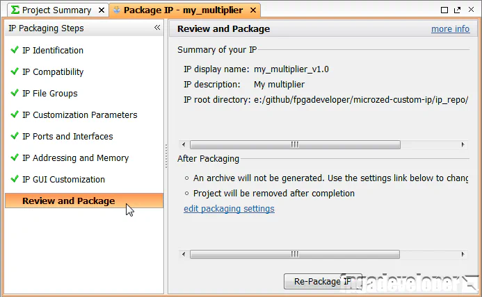
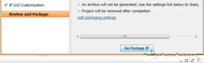
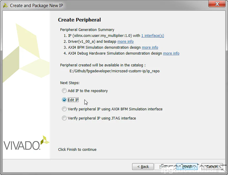
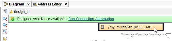
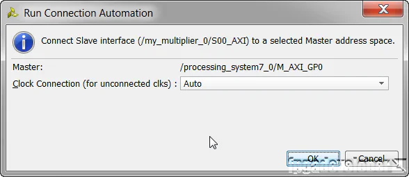
The peripheral will be packaged and the Vivado window for the peripheral should be automatically closed. We should now be able to find our IP in the IP catalog. Now the rest of this tutorial will be done from the original Vivado window.
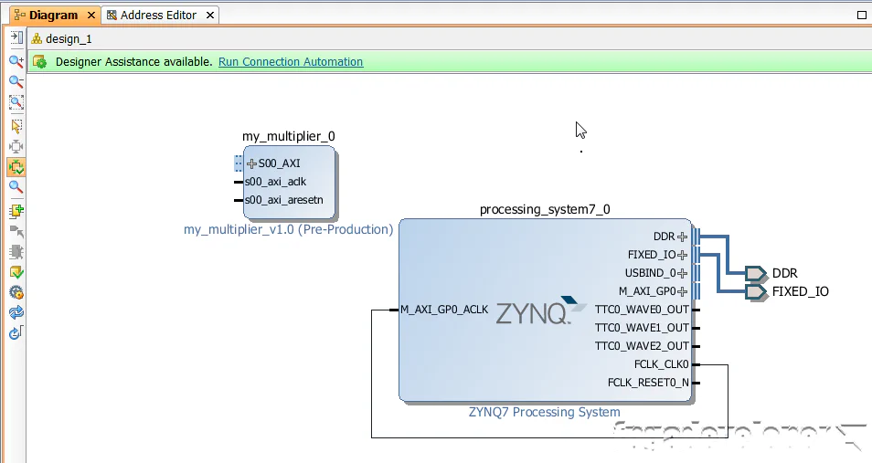
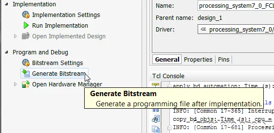
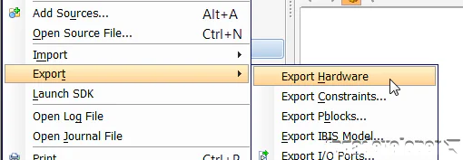
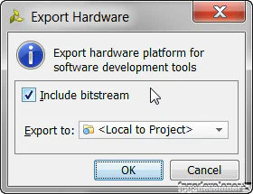
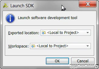
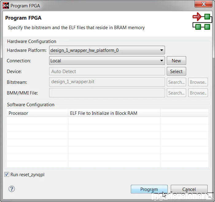
Once the bitstream has been generated, we can export our design to SDK where we can then write code for the PS. The PS is going to write data to our multiplier and read back the result.
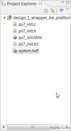
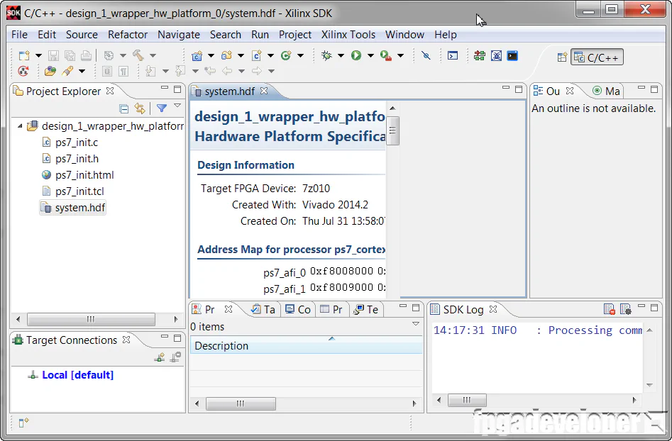
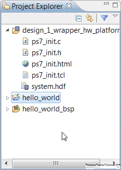
At this point, the SDK loads and a hardware platform specification will be created for your design. You should be able to see the hardware specification in the Project Explorer of SDK as shown in the image below.
You are now ready to create a software application to run on the PS.
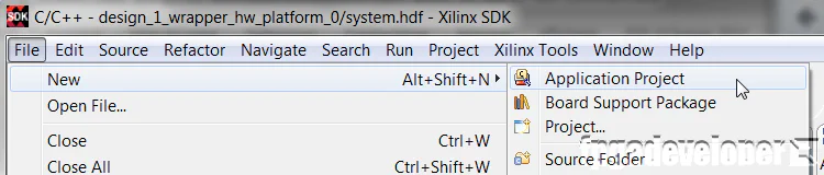
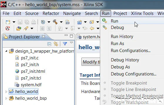
At this point, your SDK window should look somewhat like this:
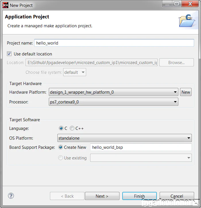
To make things easy for us, we’ll use the template for the hello world application and then modify it to test the multiplier.
hello_world. Click “Next”.
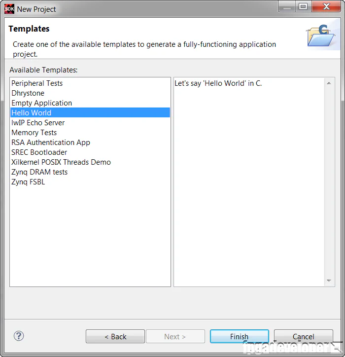
The hello_world folder contains the Hello World software application, which we will modify to test our multiplier.
Now all we need to do is modify the software application to test our multiplier peripheral.
hello_world/src folder. Open the “helloworld.c” source file.
#include "platform.h"
#include "xbasic_types.h"
#include "xparameters.h"

Xuint32 *baseaddr_p = (Xuint32 *)XPAR_MY_MULTIPLIER_0_S00_AXI_BASEADDR;

int main()
{
init_platform();

xil_printf("Multiplier Test\n\r");

// Write multiplier inputs to register 0
*(baseaddr_p+0) = 0x00020003;
xil_printf("Wrote: 0x%08x \n\r", *(baseaddr_p+0));

// Read multiplier output from register 1
xil_printf("Read : 0x%08x \n\r", *(baseaddr_p+1));

xil_printf("End of test\n\n\r");

return 0;
}
Save and close the file.
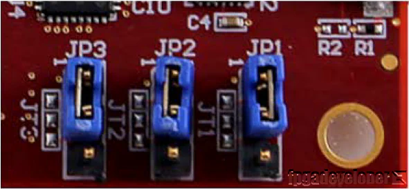
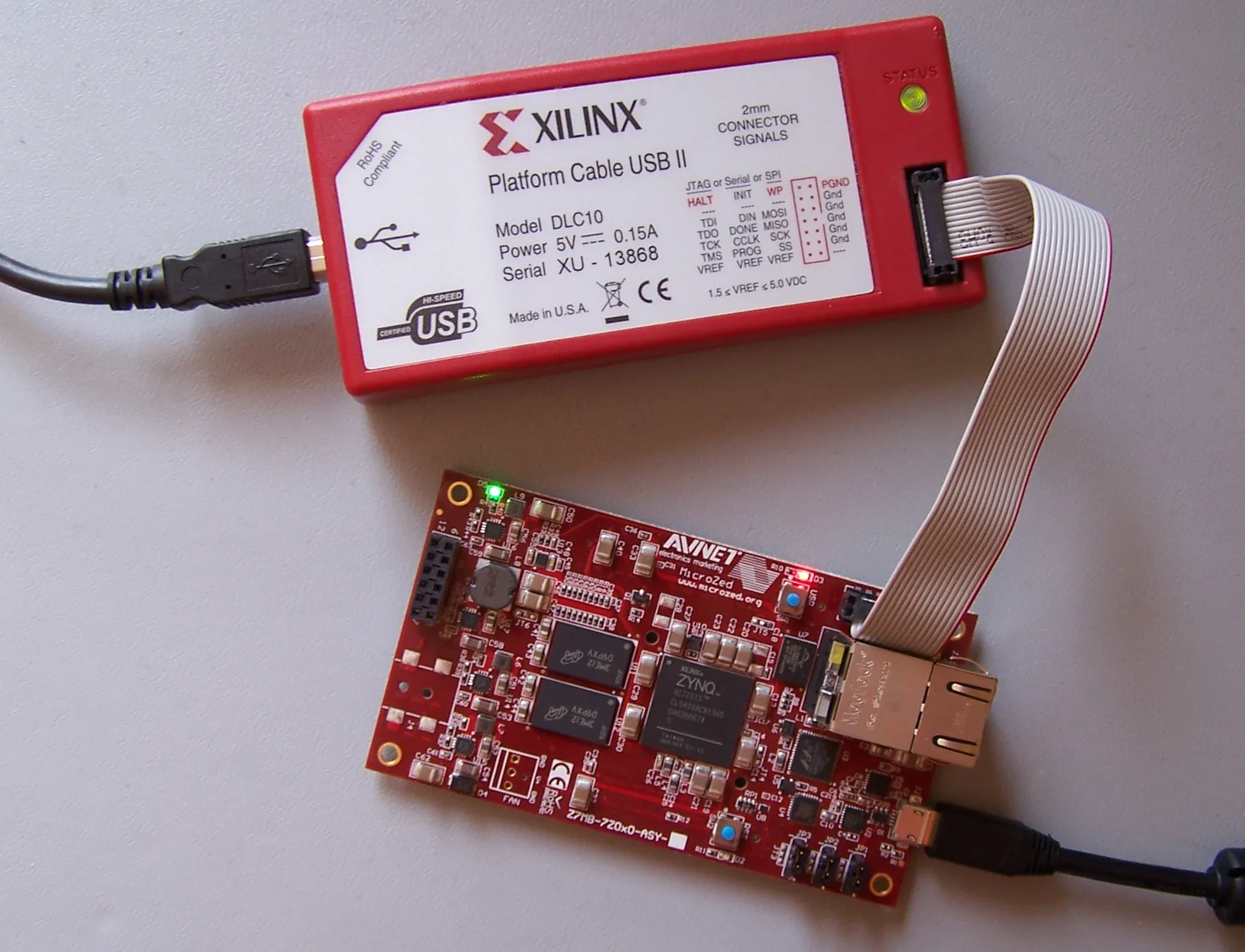
To test the design, we are using the MicroZed board from Avnet. Make the following setup before continuing:
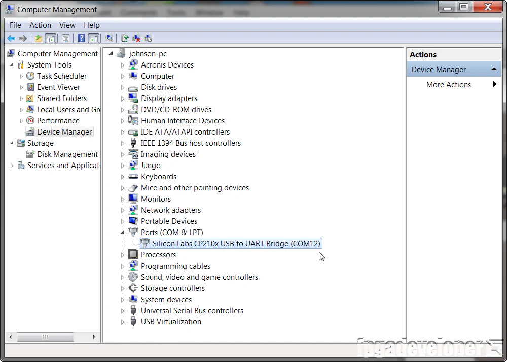
Now you need to open up a terminal program on your PC and set it up to receive the test messages. I use Miniterm because I’m a Python fan, but you could use any other terminal program such as Putty. Use the following settings:
Now that your PC is ready to receive the test messages, we are ready to send our bitstream and software application to the hardware.
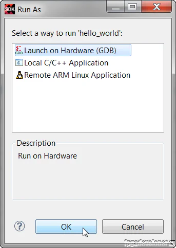
hello_world folder in the Project Explorer, then from the menu, select Run->Run.
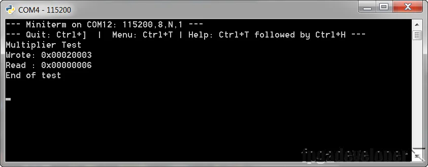
We’re sending two 16-bit inputs 0x02 and 0x03 and the result is 0x06 as expected.
The TCL build script and source code for this project is shared on Github here:
https://github.com/fpgadeveloper/microzed-custom-ip
For instructions on rebuilding the project from sources, read my post on version control for Vivado projects.