Title here
Summary here
Writing an .mcs file to Quad SPI or Linear BPI flash
January 18, 20213 minutes

Most FPGA/SoC dev boards have a flash device for non-volatile storage. Typically it would be either a Quad SPI flash (serial interface) or a Linear BPI flash (parallel interface). Although it can be used for storing anything, it’s typically used for storing the configuration for the FPGA or SoC (eg. the bitstream, FSBL, U-Boot, Linux Kernel). If the boot mode of the FPGA or SoC is appropriately set, on power-up it should read from the flash, load the bitstream into the FPGA and then load and run the software components.
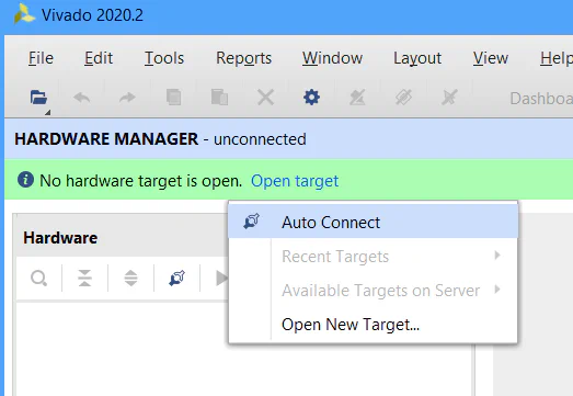
In this post we’ll look at the steps to program the flash of a dev board using Vivado Hardware Manager. I’ll be doing this for the KCU105 board, but I’ve also included a list of some popular dev boards and the appropriate flash settings to use for each.

| Board | Type | Size | Part # | Flash name |
|---|---|---|---|---|
| AC701 | QSPI | 32MB | N25Q256A13ESF40G | mt25ql256-spi-x1_x2_x4 |
| KC705 | QSPI | 16MB | N25Q128A13BSF40F | mt25qu128-spi-x1_x2_x4 |
| KC705 | BPI | 128MB | PC28F00AP30TF | 28f00ap30t-bpi-x16 |
| VC707 | BPI | 128MB | PC28F00AG18FE | mt28gu01gaax1e-bpi-x16 |
| VC709 | BPI | 128MB | PC28F00AG18FE | mt28gu01gaax1e-bpi-x16 |
| ZC702 | QSPI | 16MB | N25Q128A11ESF40G | mt25qu128-spi-x1_x2_x4 |
| ZC706 | Dual QSPI | 32MB | S25FL128SAGMFIR01 | s25fl128l-spi-x1_x2_x4_x8 |
| Board | Type | Size | Part # | Flash name |
|---|---|---|---|---|
| KCU105 | Dual QSPI | 64MB | N25Q256A11ESF40F | mt25qu256-spi-x1_x2_x4_x8 |
| KCU116 | Dual QSPI | 256MB | MT25QU01GBBB8ESF-0SIT | mt25qu01g-spi-x1_x2_x4_x8 |
| VCU108 | BPI | 128MB | MT28GU01GAAA1EGC-0SIT | mt28gu01gaax1e-bpi-x16 |
| VCU110 | Dual QSPI | 128MB | MT25QU512ABA8E12-0SIT | mt25qu512-spi-x1_x2_x4_x8 |
| VCU118 | Dual QSPI | 256MB | MT25QU01GBB8ESF | mt25qu01g-spi-x1_x2_x4_x8 |
| VCU118 | BPI | 128MB | MT28GU01GAAA1EGC-0SIT | mt28gu01gaax1e-bpi-x16 |
| Board | Type | Size | Part # | Flash name |
|---|---|---|---|---|
| ZCU104 | QSPI | 64MB | MT25QU512ABB8ESF | mt25qu512-spi-x1_x2_x4 |
| ZCU102 | Dual QSPI | 128MB | MT25QU512ABB8ESF | mt25qu512-spi-x1_x2_x4_x8 |
| ZCU106 | Dual QSPI | 128MB | MT25QU512ABB8ESF | mt25qu512-spi-x1_x2_x4_x8 |
| ZCU111 | Dual QSPI | 512MB | MT25QU02GCBB8E12-0sit | mt25qu02g-spi-x1_x2_x4_x8 |
| Board | Type | Size | Part # | Flash name |
|---|---|---|---|---|
| Arty A7 | QSPI | 16MB | N25Q128A13ESF40 | mt25ql128-spi-x1_x2_x4 |
| PYNQ Z1 | QSPI | 16MB | S25FL128SAGMFI00 | s25fl128sxxxxxx0-spi-x1_x2_x4 |
| PYNQ Z2 | QSPI | 16MB | S25FL128S | s25fl128sxxxxxx0-spi-x1_x2_x4 |
| ZedBoard | QSPI | 32MB | S25FL256S | s25fl256sxxxxxx0-spi-x1_x2_x4 |
| MicroZed | QSPI | 16MB | S25FL128SAGBHI200 | s25fl128sxxxxxx0-spi-x1_x2_x4 |
| Z-Turn | QSPI | 16MB | W25Q128BVFIG | mt25ql128-spi-x1_x2_x4 |
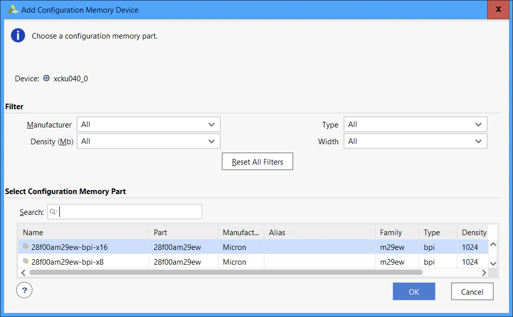
You might notice that the flash names listed above are all proceeded by x1_x2_x4
or x1_x2_x4_x8. The latter postfix is used for dual quad SPI interfaces, where two
Quad SPI devices are connected to an 8 bit wide interface. However, just because there
are 2 Quad SPI flashes connected, doesn’t mean that you have to use them both. If you
wanted to use the first Quad SPI device only, then you should use the x1_x2_x4 postfix.
.mcs and .prm files to program the flash with. Note that
in my case, I’m programming the KCU105’s flash in dual Quad SPI mode, which means that
I need two .mcs files and two .prm files. If you are not using dual Quad SPI mode, then
you will only have the option to select one of each file.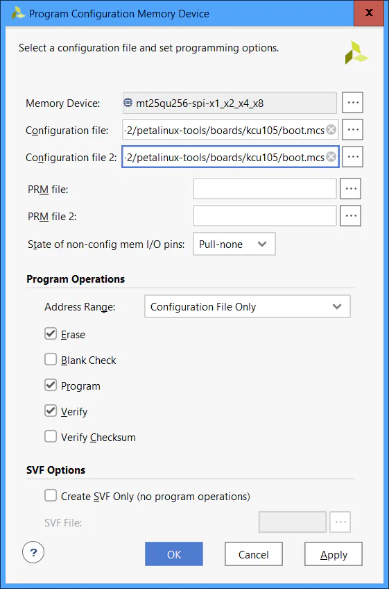
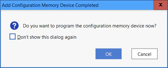
After clicking “OK”, the Vivado Hardware Manager should program your board’s flash and verify that it was programmed correctly.