Title here
Summary here
Tutorial on setting up and testing the AXI DMA engine in a Vivado design targeting the MicroZed.
August 6, 20149 minutes

Update 2017-10-10: I’ve turned this tutorial into a video here for Vivado 2017.2. In a previous tutorial I went through how to use the AXI DMA Engine in EDK, now I’ll show you how to use the AXI DMA in Vivado. We’ll create the hardware design in Vivado, then write a software application in the Xilinx SDK and test it on the MicroZed board (source code is shared on Github for the MicroZed and the ZedBoard, see links at the bottom).
DMA stands for Direct Memory Access and a DMA engine allows you to transfer data from one part of your system to another. The simplest usage of a DMA would be to transfer data from one part of the memory to another, however a DMA engine can be used to transfer data from any data producer (eg. an ADC) to a memory, or from a memory to any data consumer (eg. a DAC).
In this design, we’ll use the DMA to transfer data from memory to an IP block and back to the memory. In principle, the IP block could be any kind of data producer/consumer such as an ADC/DAC FMC, but in this tutorial we will use a simple FIFO to create a loopback. After, you’ll be able to break the loop and insert whatever custom IP you like.
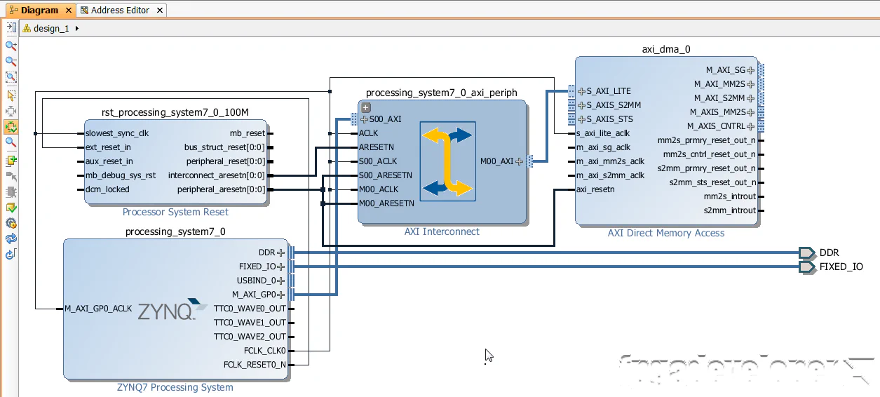
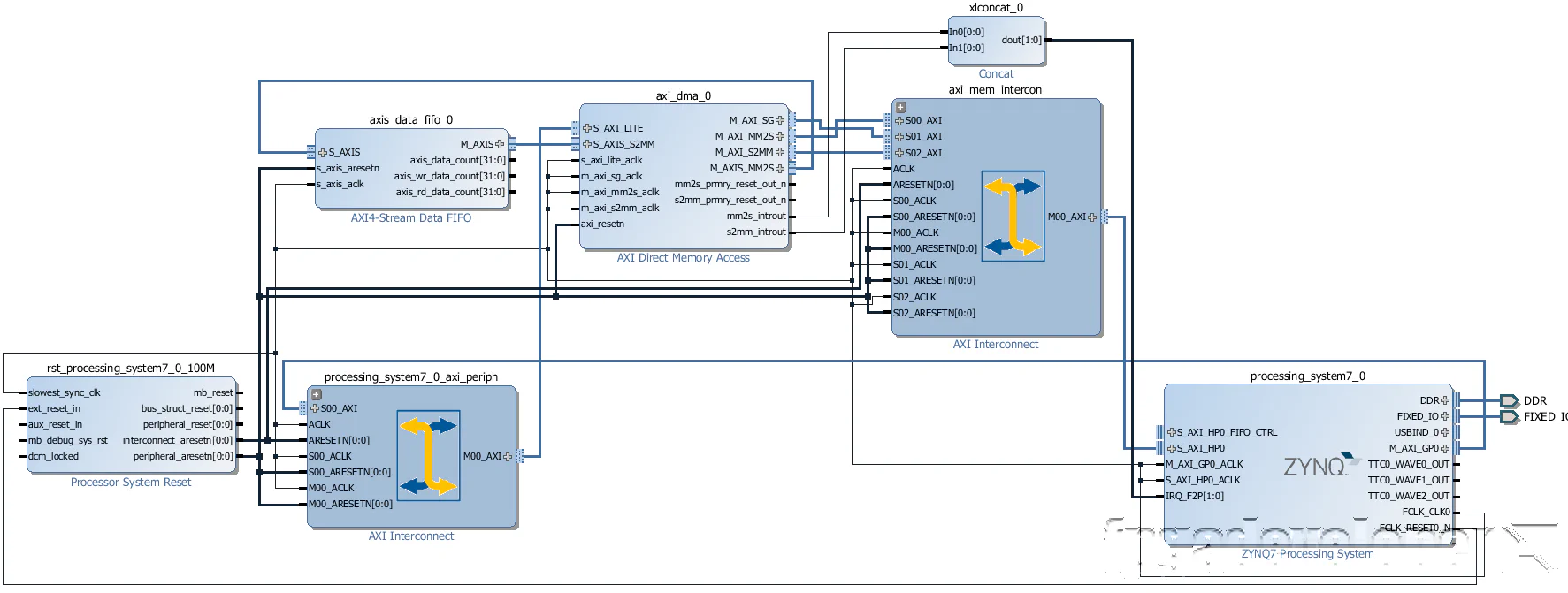
 The block diagram above illustrates the design that we’ll create. The processor and DDR memory controller are contained within the Zynq PS. The AXI DMA and AXI Data FIFO are implemented in the Zynq PL. The AXI-lite bus allows the processor to communicate with the AXI DMA to setup, initiate and monitor data transfers. The AXI_MM2S and AXI_S2MM are memory-mapped AXI4 buses and provide the DMA access to the DDR memory. The AXIS_MM2S and AXIS_S2MM are AXI4-streaming buses, which source and sink a continuous stream of data, without addresses.
Notes:
Before following this tutorial, you will need to do the following:
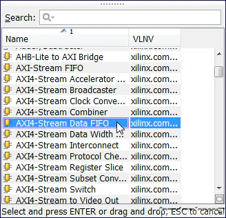
We’ll start this tutorial with the base system project for the MicroZed that you can access here:
Base system project for the MicroZed
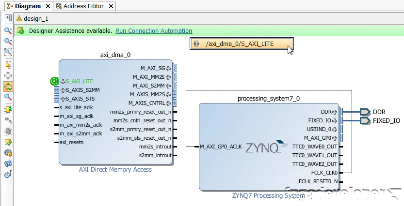
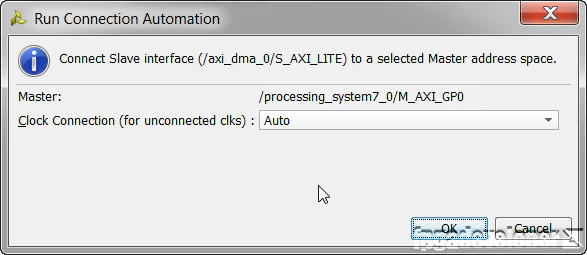
/axi_dma_0/S_AXI_LITE from the drop-down menu.
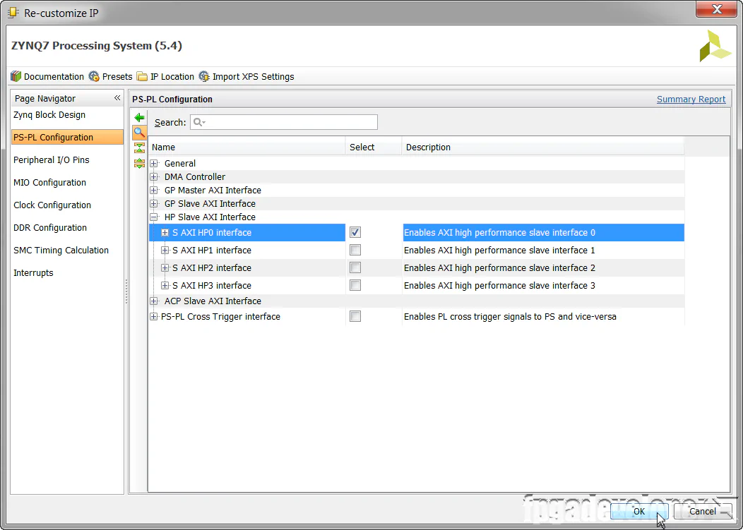
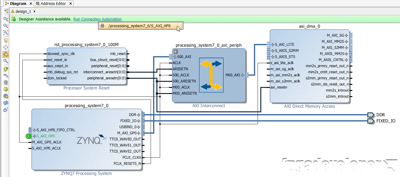
/processing_system7_0/S_AXI_HP0 from the drop-down menu.

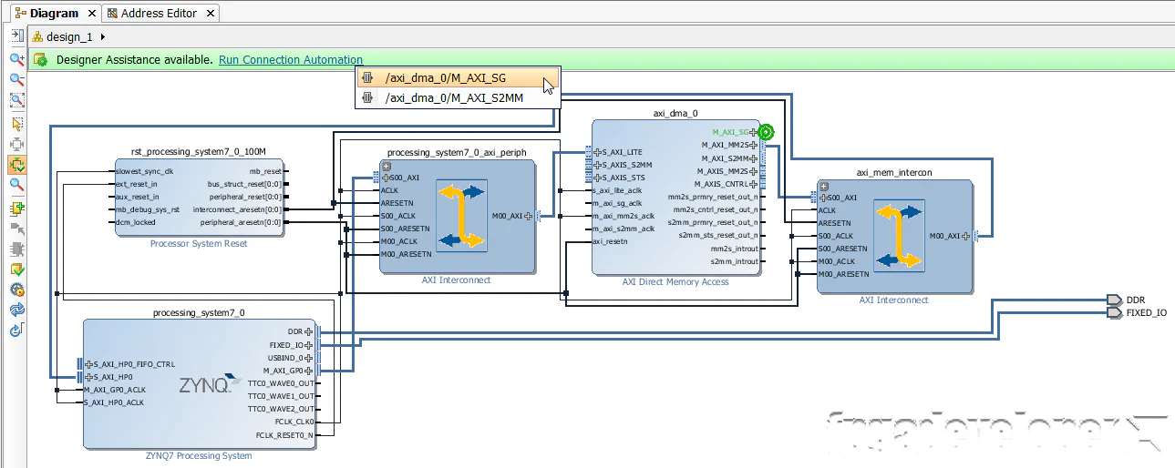
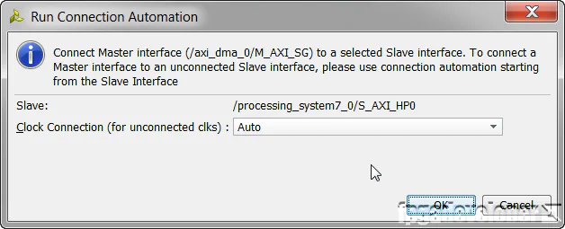
/axi_dma_0/M_AXI_SG from the drop-down menu.
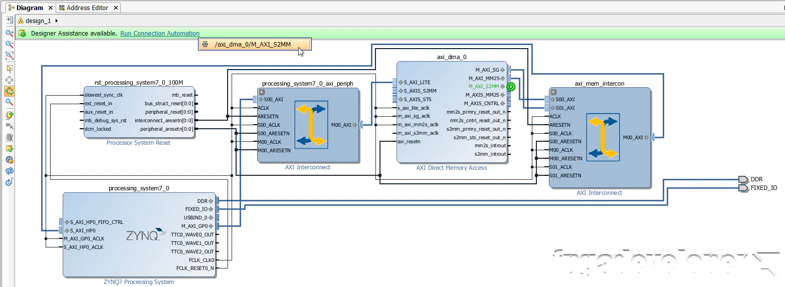
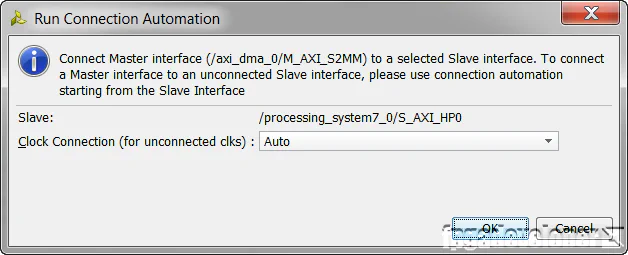
/axi_dma_0/M_AXI_S2MM from the drop-down menu.
Now all the memory-mapped AXI buses are connected to the DMA. Now we only have to connect the AXI streaming buses to our loopback FIFO and connect the DMA interrupts.
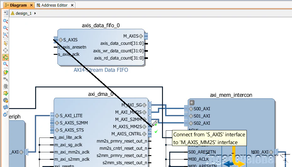
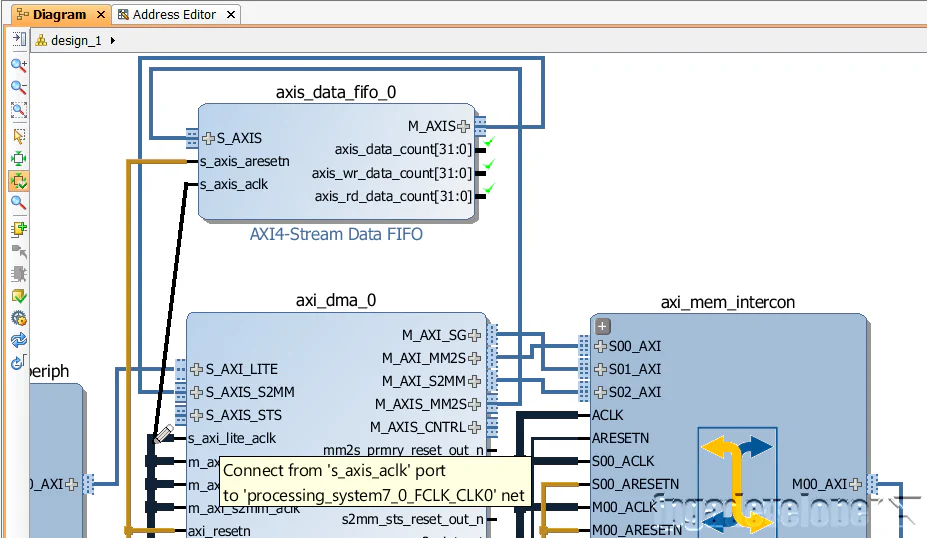
S_AXIS port on the FIFO and connect it to the M_AXIS_MM2S port of the DMA.
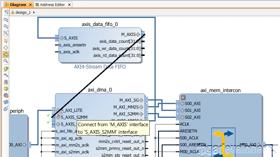
M_AXIS port on the FIFO and connect it to the S_AXIS_S2MM port of the DMA.
s_axis_aresetn port of the FIFO and connect it to the axi_resetn port of the DMA.
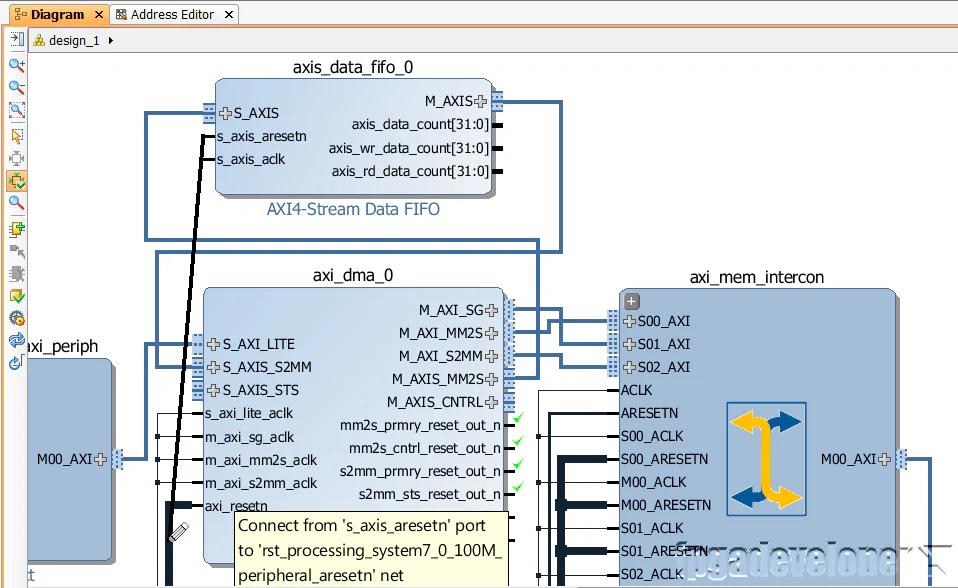
s_axis_aclk port of the FIFO and connect it to the s_axi_lite_aclk port of the DMA.
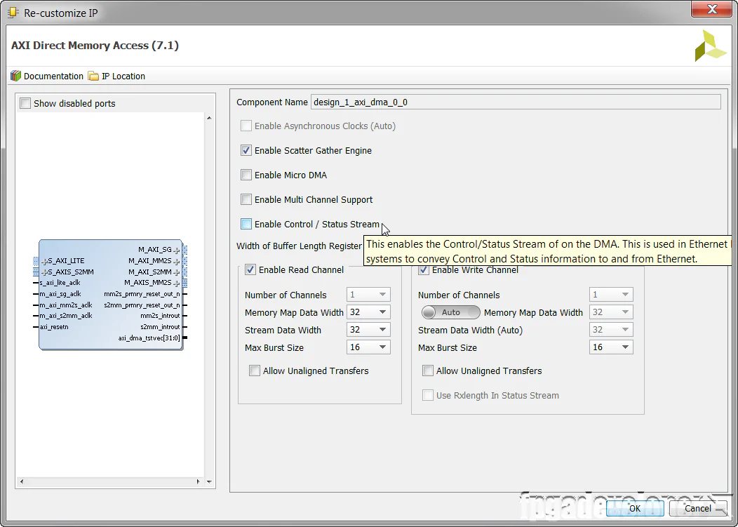
In our design, we won’t need the AXI-Streaming status and control ports which are used to transmit extra information alongside the data stream. You might use them if you were connecting to the AXI Ethernet core or a custom IP that made use of them.
Our software application will test the DMA in polling mode, but to be able to use it in interrupt mode, we need to connect the interrupts mm2s_introut and s2mm_introut to the Zynq PS.
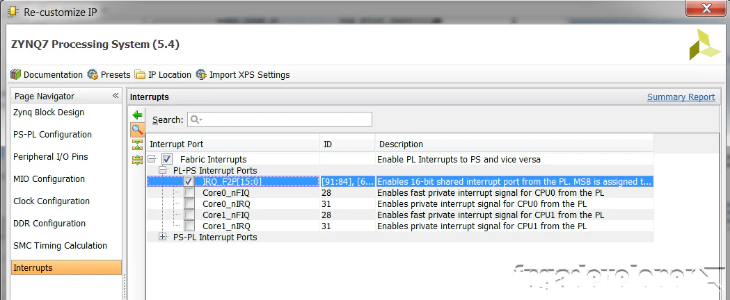
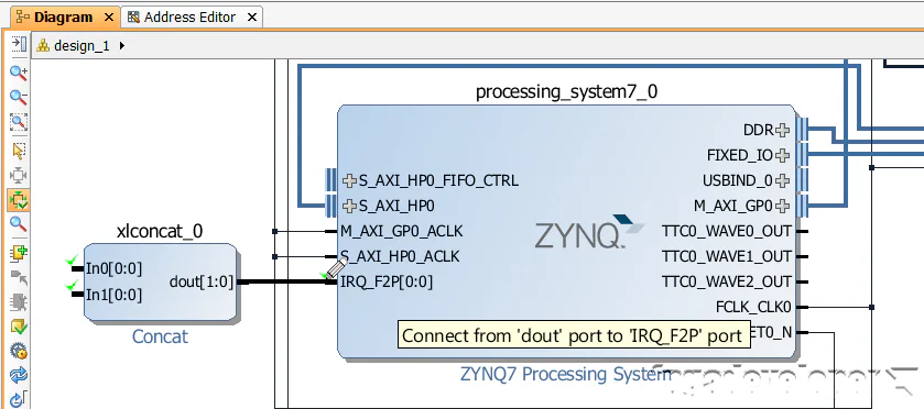
IRQ_F2P[15:0] to enable them, and click OK.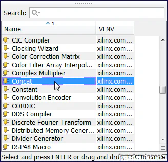
dout port of the Concat to the IRQ_F2P port of the Zynq PS.
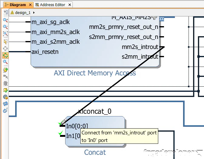
mm2s_introut port of the DMA to the In0 port of the Concat.
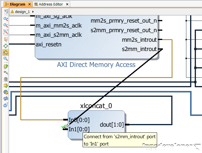
s2mm_introut port of the DMA to the In1 port of the Concat.
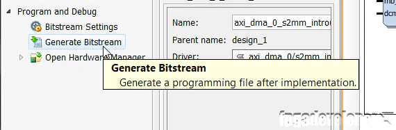
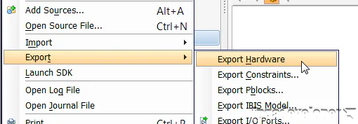
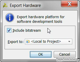
Once the bitstream has been generated, we can export our design to SDK where we can develop the software application that will setup a DMA transfer, wait for completion and then verify the loopback.
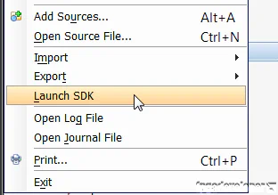
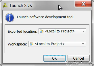
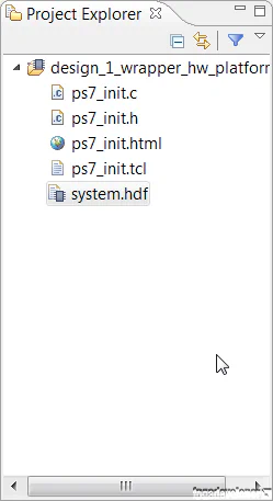
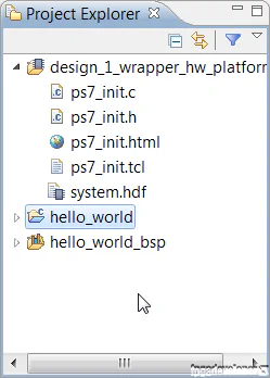
At this point, the SDK loads and a hardware platform specification will be created for your design. You should be able to see the hardware specification in the Project Explorer of SDK as shown in the image below.
We are now ready to create the software application.
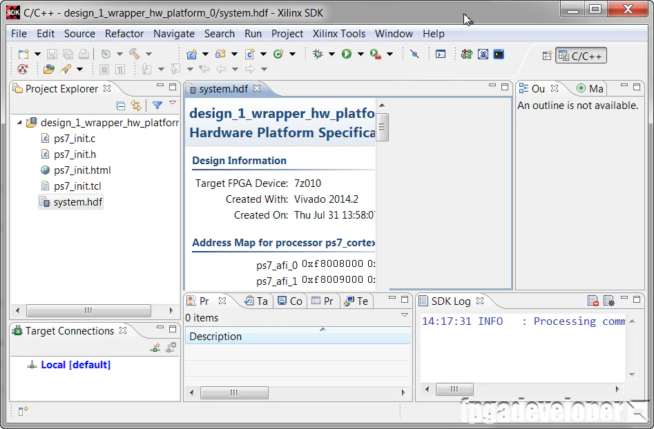
At this point, your SDK window should look somewhat like this:
To make things easy for us, we’ll use the template for the hello world application and then modify it to test the AXI DMA.
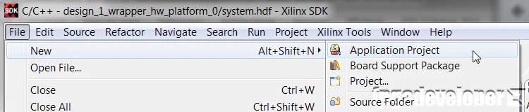
hello_world. Click “Next”.
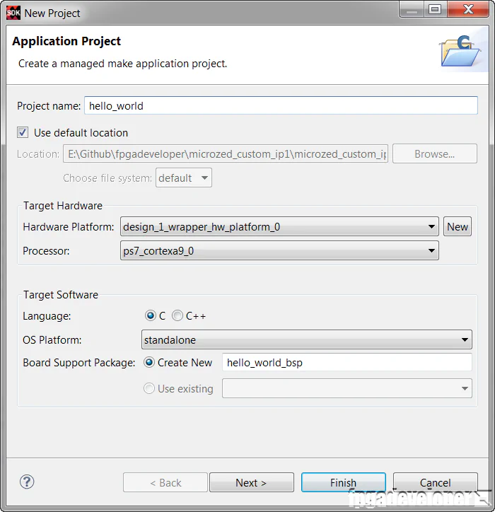
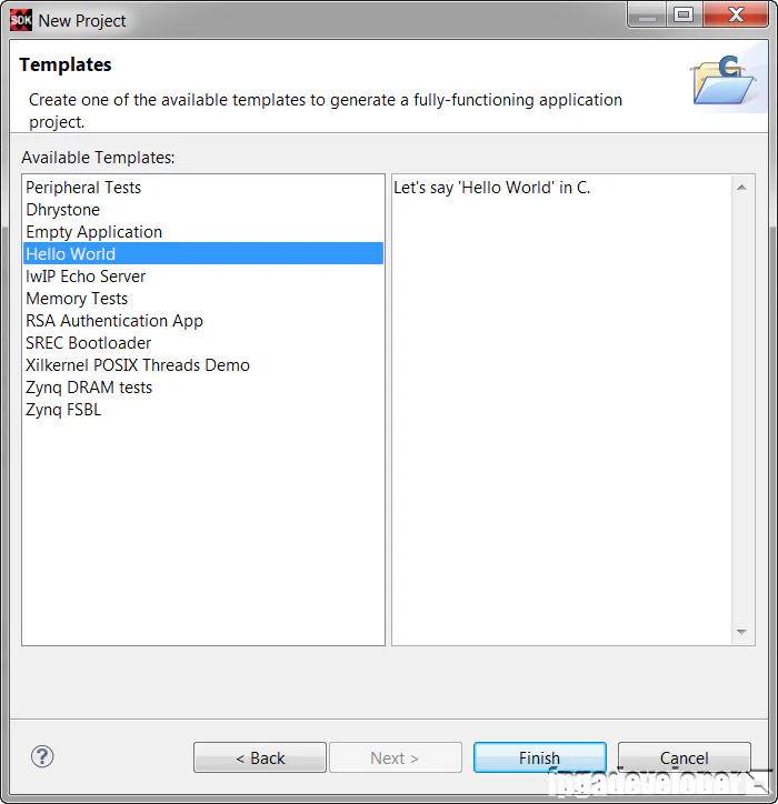
The hello_world folder contains the Hello World software application, which we will modify to test our AXI DMA.
We need to modify the hello world software application to test our DMA.
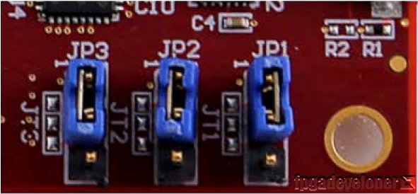
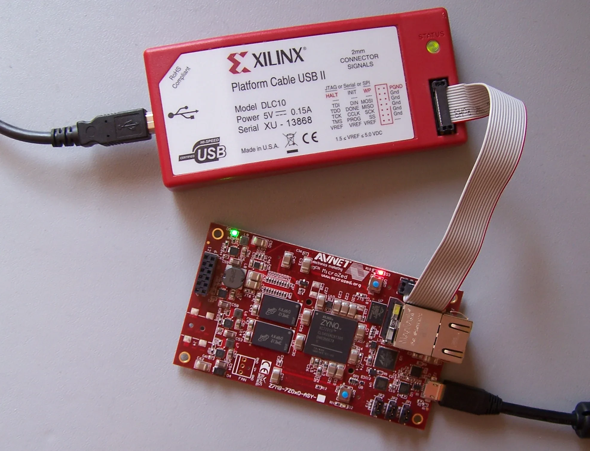
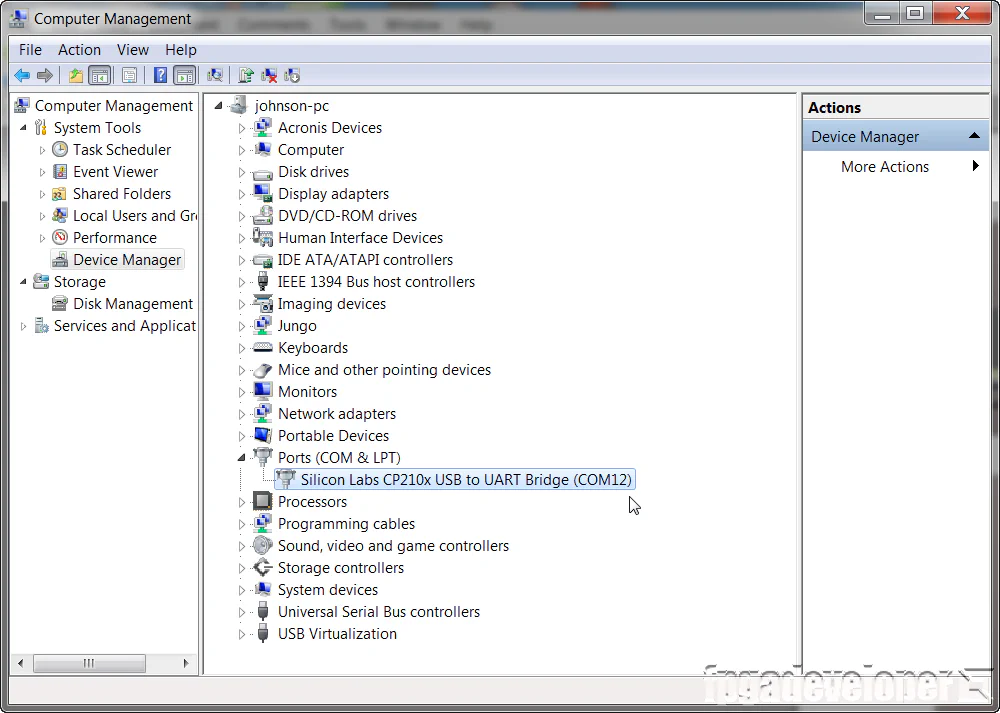
hello_world/src folder. Open the “helloworld.c” source file.C:\Xilinx\SDK\(version)\data\embeddedsw\XilinxProcessorIPLib\drivers\axidma_v(ver)\examples\xaxidma_example_sg_poll.cTo test the design, we are using the MicroZed board from Avnet. Make the following setup before continuing:
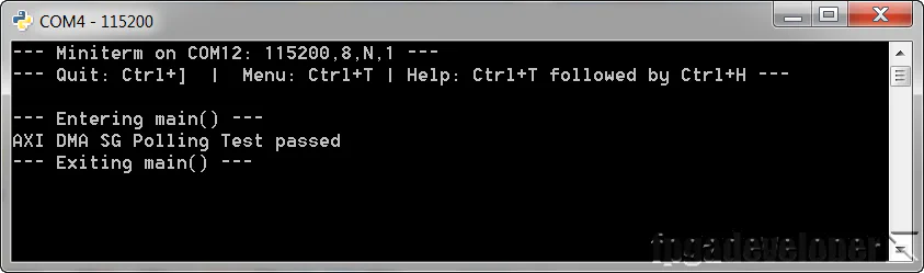
Now you need to open up a terminal program on your PC and set it up to receive the test messages. I use Miniterm because I’m a Python fan, but you could use any other terminal program such as Putty. Use the following settings:
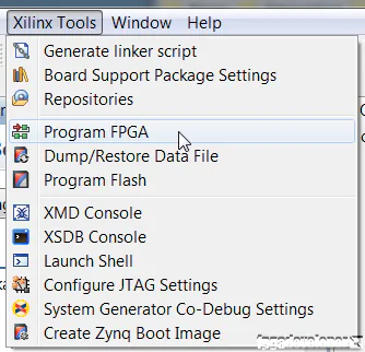
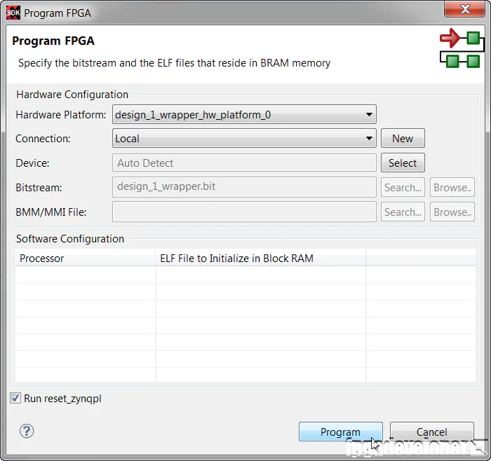
Now that your PC is ready to receive the test messages, we are ready to send our bitstream and software application to the hardware.
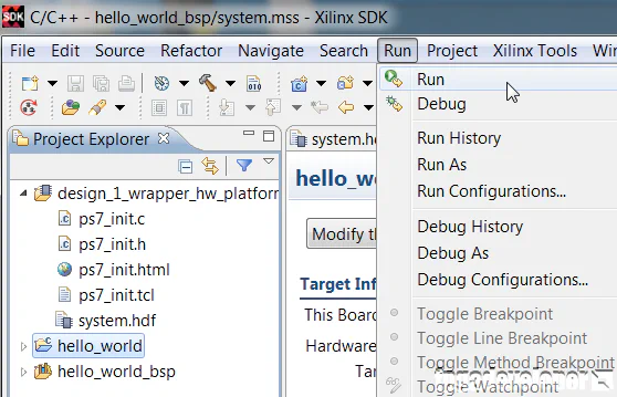
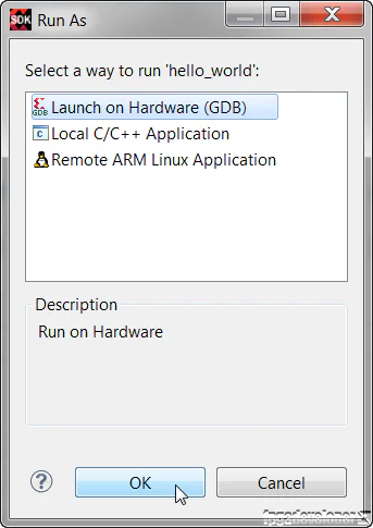
hello_world folder in the Project Explorer, then from the menu, select Run->Run.
The TCL build script and source code for this project is shared on Github at the following links:
For instructions on rebuilding the project from sources, read my post on version control for Vivado projects.