Title here
Summary here
Modularizing the TEMAC example design
April 20, 20219 minutes

On one of the last posts we used the example design generated by Vivado for the tri_mode_ethernet_mac_ip, and we changed the port used by the example to one of the ports of the Ethernet FMC board. This time, we are going to modify the example design in order to make it easy to replicate the example project on the 4 ports of the FMC Ethernet. To do that, we will need to extract from the example the blocks that will be shared by all ports, and also modify the IP configuration in order to use the less different modules possible.
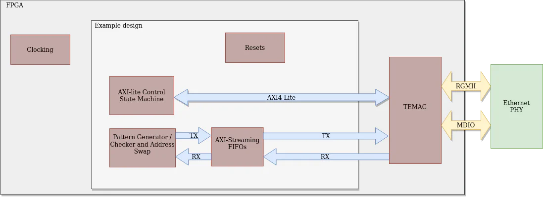
The example project contains 3 main blocks that can be separate. The first one is the block which generates the clocks signals. This block in the example is named as tri_mode_ethernet_mac_0_example_design_clocks.v. The second block will be the tri_mode_ethernet_mac_ip, which is in charge of the interface with the PHY. And last, the third block will be in charge of all the logic of the example including FIFOs, AXI4 interface and resets, and will contain all the rest of the module of the project. This block will be composer for the rest of the modules of the example, and the top module will be the top module of the example, tri_mode_ethernet_mac_0_example_design.
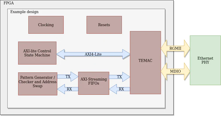
The goal this project we will separate the design in three different blocks, create a block design with this modules instantiated and test the new model to check that the behavior is the same than the original example.
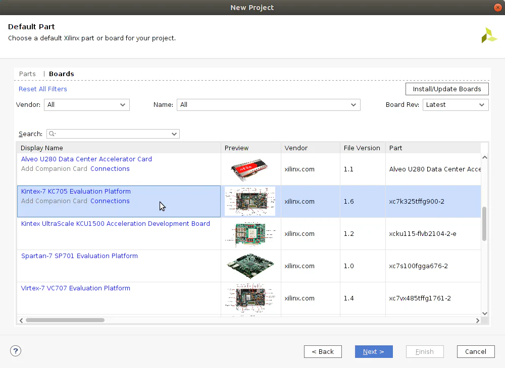
In order to generate the TEMAC IP, as we did on the last post, we need to generate a new Vivado project for the KC705 board, without adding any module or file.
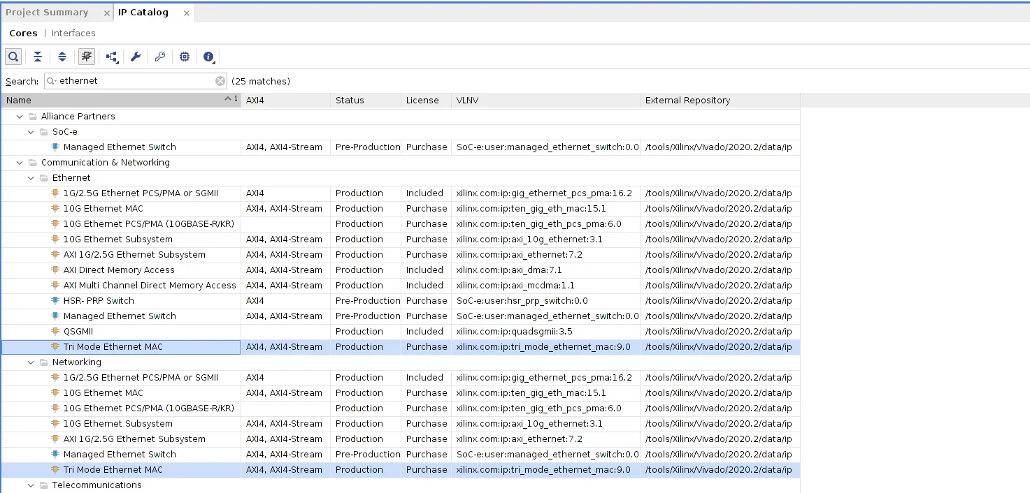
Once the project is created, we have to add the TEMAC IP to the project. To do that we will open the IP catalog, then we will search for ethernet on the search box, and last we have to select Tri Mode Ethernet MAC.
Now we are going to configurate the IP. This process will be different than the other post, because in this case, we want to allow use more than one TEMAC IP.
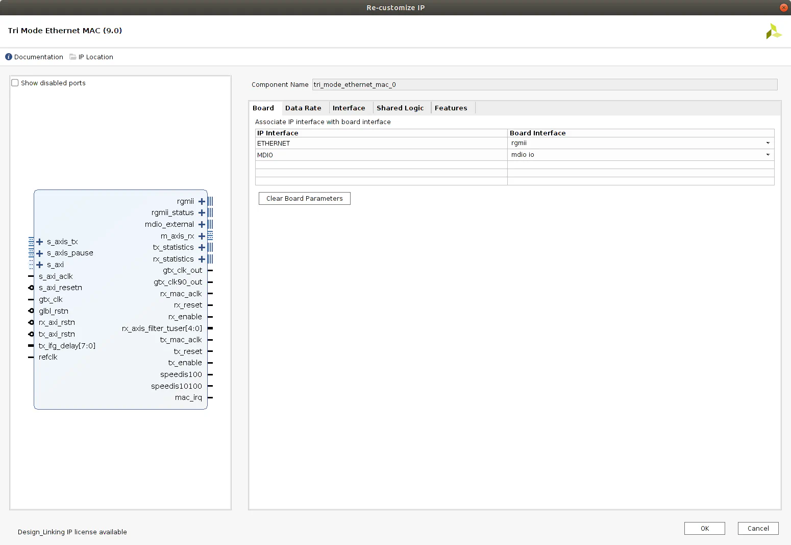
On the first tab, we have to select rgmii as ETHERNET interface, and mdio io as MDIO interface.
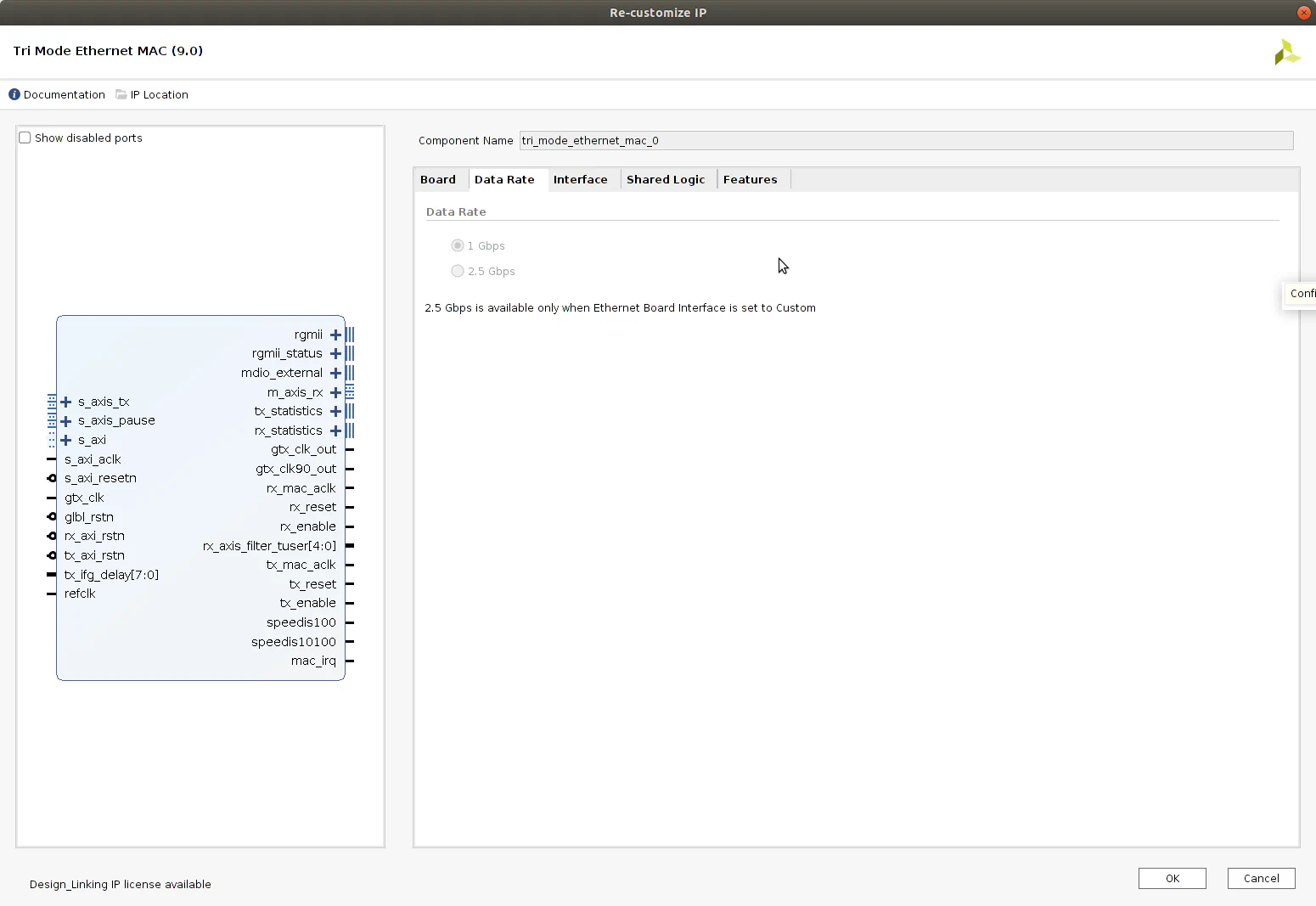
On the next tab, the speed of the ethernet link are pre-selected and grayed.
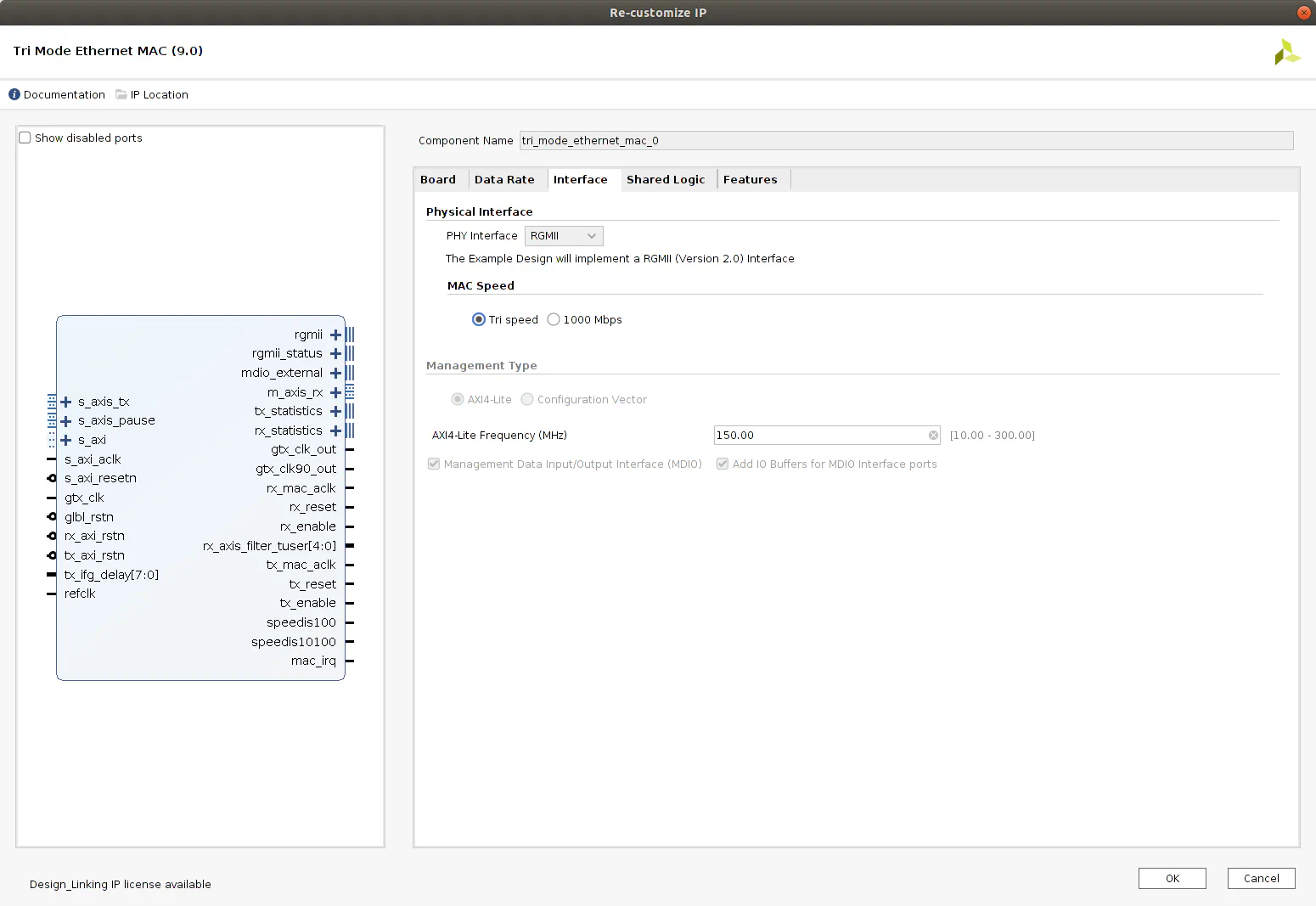
On the interface tab, the configuration by default will be valid.
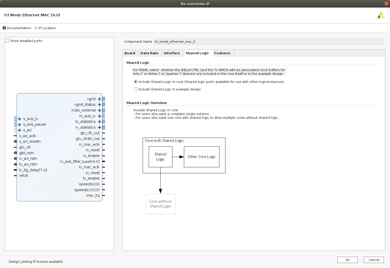
The next tab is to configure if we want that the IP will contain all the logic needed for the IP, that can be used for other TEMAC IP, or we want to use the logic generated externally to the IP. For this IP, this external logic are the MMCM block to generate the RGMII clocks, an IDELAY block, and a synchronous reset block. On this case, we will select Include shared logic in core. This option will allow us to use the same management modules in case that we want to replicate the example in more than one port. That’s because if we select the other option, the MCMM module and the rest of the shared modules are generated on the example design, and if we do that then we have 2 options. Keep the logic inside the management module, and replicate it for all ports, using one MCMM per port, or we can extract from the example design the 3 blocks of the shared logic, and add it to the design, increasing the number of blocks of the design. Using the option Include shared logic in core, the MCMM blocks are included inside the IP, and the clocks are accesible from outside the IP, therefore when we will add new TEMAC IPs to the design, we will select the option Include shared logic in the example design, and we can share the MCMM included on the first TEMAC IP with the rest of the modules.
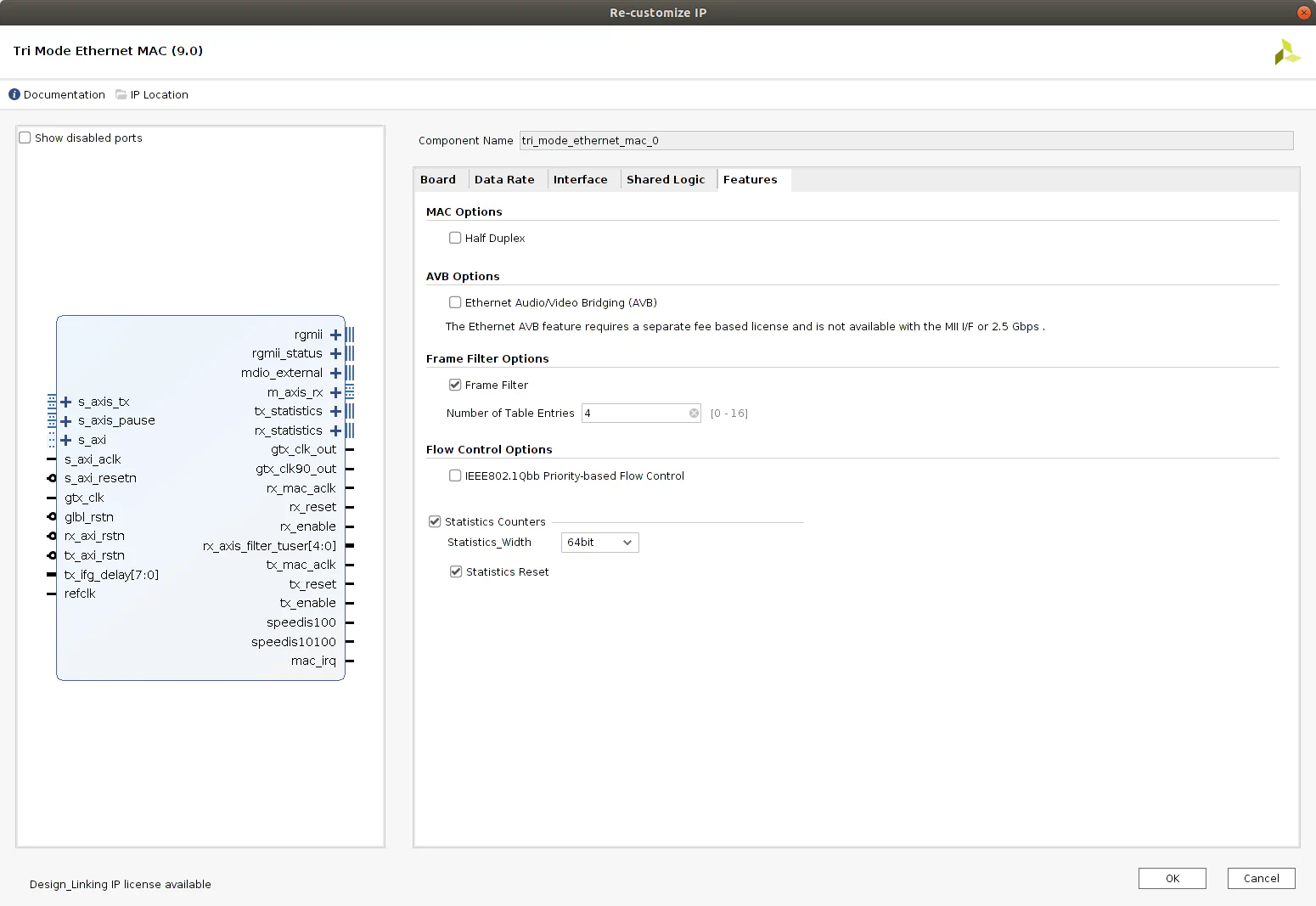
Finally, the tab Features will remain as default.
Once the IP if configured, Vivado will ask if we want to generate the output, and we have to click on Generate. When the IP will be generated, the next is generate the example design. To do that, we will click with the right button over the IP and select Open IP Example Design
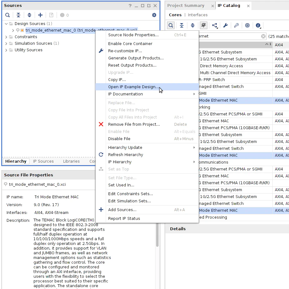
Now, we can select the folder where we want to save the project, but the name of the project is fixed. When the project will be generated, Vivado will open the example project.
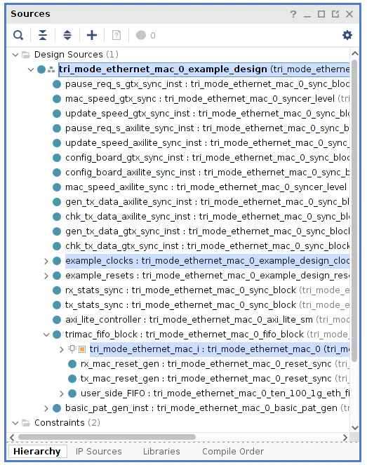
The next we have to do is modify the example project. First we will take a look to the files that the example project contains. We can see a top module named tri_mode_ethernet_mac_0_example_design, and inside this module we can find the module tri_mode_ethernet_mac_0_example_design_clocks, which contains the MCMM for the global clocks. Also, inside the module tri_mode_ethernet_mac_0_fifo_block, we can find the IP tri_mode_ethernet_mac instantiated.
In order to allow generate a multi-port project, as we saw on the diagrams, we have extract from the example design the module tri_mode_ethernet_mac_0_example_design_clocks and the IP. Lets start with the clocks module. On top module, we can see the instantiation.
//----------------------------------------------------------------------------
// Clock logic to generate required clocks from the 200MHz on board
// if 125MHz is available directly this can be removed
//----------------------------------------------------------------------------
 tri_mode_ethernet_mac_0_example_design_clocks example_clocks
  (
     // differential clock inputs
     .clk_in_p         (clk_in_p),
     .clk_in_n         (clk_in_n),

     // asynchronous control/resets
     .glbl_rst         (glbl_rst),
     .dcm_locked       (dcm_locked),

     // clock outputs
     .gtx_clk_bufg     (gtx_clk_bufg),
     .refclk_bufg      (refclk_bufg),
     .s_axi_aclk       (s_axi_aclk)
  );
This module has 2 inputs for the input differential clock, one reset input, and 3 outputs clocks and a locked output port. On our new design, the differential clock and the global reset inputs will be connected externally, and the output clocks and locked port will be connected to the other modules. On the example design module, we have to add the inputs for the clocks and the lockd signal.
// Input clocks from design clocks
input         gtx_clk_bufg,
input         refclk_bufg,
input         s_axi_aclk,

// locked signal from design clocks
input         dcm_locked,
Now, we can supply the clocks externally to the module.
Next we have to take the TEMAC IP out of the module tri_mode_ethernet_mac_0_fifo_block and also out of the example design. To do that, first we will comment on the tri_mode_ethernet_mac_0_fifo_block all the connections to the PHY, since thet will be done outside the example design.
// MAC Control Interface
//------------------------
// input         pause_req,
// input  [15:0] pause_val,

// RGMII Interface
//------------------
// output [3:0]  rgmii_txd,
// output        rgmii_tx_ctl,
// output        rgmii_txc,
// input  [3:0]  rgmii_rxd,
// input         rgmii_rx_ctl,
// input         rgmii_rxc,

// RGMII Inband Status Registers
//--------------------------------
// output        inband_link_status,
// output [1:0]  inband_clock_speed,
// output        inband_duplex_status,


// // MDIO Interface
// //---------------
// inout         mdio,
// output        mdc,
Now, we have to take out the module the AXI-Stream interface from the FIFOs.
// rx mac AXI-Stream interface
input    [7:0]    rx_axis_mac_tdata,
input             rx_axis_mac_tvalid,
input             rx_axis_mac_tlast,
input             rx_axis_mac_tuser,

// tx mac AXI-Stream interface
output   [7:0]    tx_axis_mac_tdata,
output            tx_axis_mac_tvalid,
output            tx_axis_mac_tlast,
input             tx_axis_mac_tready,
output            tx_axis_mac_tuser
The next is to comment the AXI4-Lite interface to configure TEMAC IP.
// AXI-Lite Interface
// //---------------
// input         s_axi_aclk,
// input         s_axi_resetn,
//
// input  [11:0] s_axi_awaddr,
// input         s_axi_awvalid,
// output        s_axi_awready,
//
// input  [31:0] s_axi_wdata,
// input         s_axi_wvalid,
// output        s_axi_wready,
//
// output [1:0]  s_axi_bresp,
// output        s_axi_bvalid,
// input         s_axi_bready,
//
// input  [11:0] s_axi_araddr,
// input         s_axi_arvalid,
// output        s_axi_arready,
//
// output [31:0] s_axi_rdata,
// output [1:0]  s_axi_rresp,
// output        s_axi_rvalid,
// input         s_axi_rready
We can see several signals which are generated by the TEMAC IP, and are used inside the module tri_mode_ethernet_mac_0_fifo_block and also on the rest of the design. This signals, that originally are outputs, must be converted to inputs since the TEMAC IP will be instantiated outside. And signals generated by TEMAC IP used outside the module, can be deleted.
// Receiver Statistics Interface
//---------------------------------------
// output        rx_mac_aclk,
// output        rx_reset,
// output [27:0] rx_statistics_vector,
// output        rx_statistics_valid,

input        rx_mac_aclk,
input        rx_reset,

// Transmitter Statistics Interface
//------------------------------------------
// output        tx_mac_aclk,
// output        tx_reset,
// input  [7:0]  tx_ifg_delay,
// output [31:0] tx_statistics_vector,
// output        tx_statistics_valid,
input        tx_mac_aclk,
input        tx_reset,
Now we have the tri_mode_ethernet_mac_0_fifo_block module ready. The next is modify the top module tri_mode_ethernet_mac_0_example_design. On this module we have to create the AXI4-Lite interface, the AXI Stream and the signals that are connected to the TEMAC IP.
// Pause interface DESerialisation
output reg                  pause_req,
output reg   [15:0]         pause_val,

// Receiver Statistics Interface
//---------------------------------------
input        rx_mac_aclk,
input        rx_reset,
input [27:0] rx_statistics_vector,
input        rx_statistics_valid,

// rx mac AXI-Stream interface
input    [7:0]    rx_axis_mac_tdata,
input             rx_axis_mac_tvalid,
input             rx_axis_mac_tlast,
input             rx_axis_mac_tuser,

// Transmitter Statistics Interface
//------------------------------------------
input        tx_mac_aclk,
input        tx_reset,
output  [7:0]  tx_ifg_delay,
input [31:0] tx_statistics_vector,
input        tx_statistics_valid,

// tx mac AXI-Stream interface
output   [7:0]    tx_axis_mac_tdata,
output            tx_axis_mac_tvalid,
output            tx_axis_mac_tlast,
input             tx_axis_mac_tready,
output            tx_axis_mac_tuser,

// AXI-Lite Interface
//---------------
output         s_axi_resetn,

output  [11:0] s_axi_awaddr,
output         s_axi_awvalid,
input        s_axi_awready,

output  [31:0] s_axi_wdata,
output         s_axi_wvalid,
input        s_axi_wready,

input [1:0]  s_axi_bresp,
input        s_axi_bvalid,
output         s_axi_bready,

output  [11:0] s_axi_araddr,
output         s_axi_arvalid,
input        s_axi_arready,

input [31:0] s_axi_rdata,
input [1:0]  s_axi_rresp,
input        s_axi_rvalid,
output         s_axi_rready
Notice that some of this signals are declared as registers or wires on this module, so we will need to delete or comment this declarations. Now, as we did with the other module, we have to delete the interface with the PHY, since this will be done by the external TEMAC IP.
// RGMII Interface
//----------------
// output [3:0] rgmii_txd,
// output rgmii_tx_ctl,
// output rgmii_txc,
// input [3:0] rgmii_rxd,
// input rgmii_rx_ctl,
// input rgmii_rxc,
// MDIO Interface
//---------------
// inout mdio,
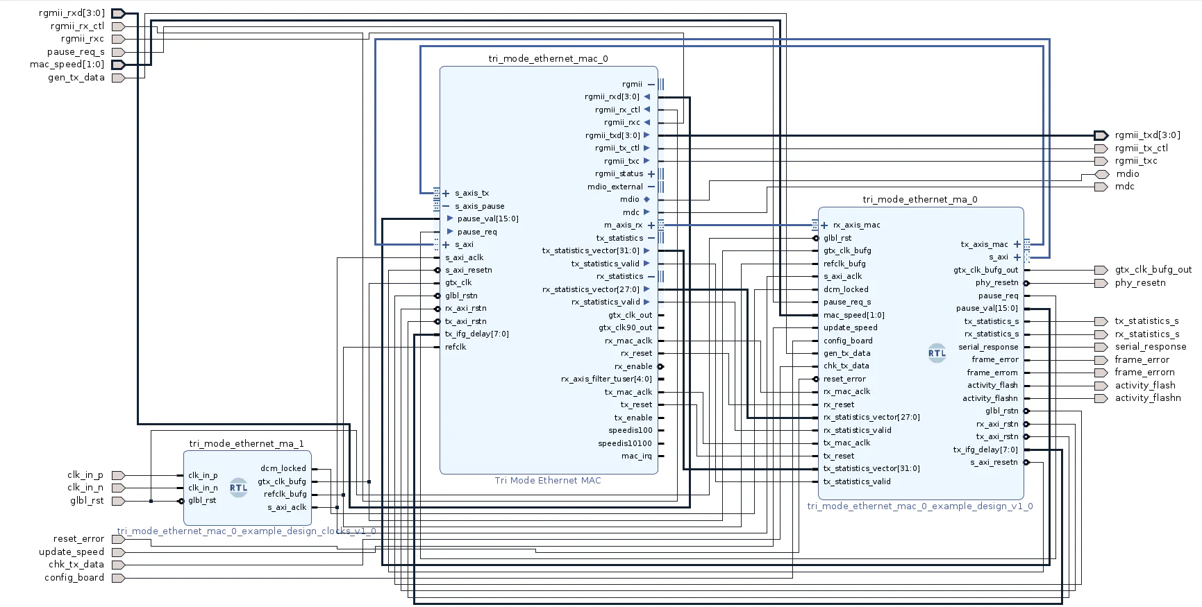
// output mdc,Finally, with this modifications done, we can create a new block design, and add the modules tri_mode_ethernet_mac_0_example_design, tri_mode_ethernet_mac_0_example_design_clocks.v and the TEMAC IP, and connect all the ports. The resulting block design will look like the next.
This is a 3 part tutorial (you’ve just read the 2nd):