Tutorial Overview
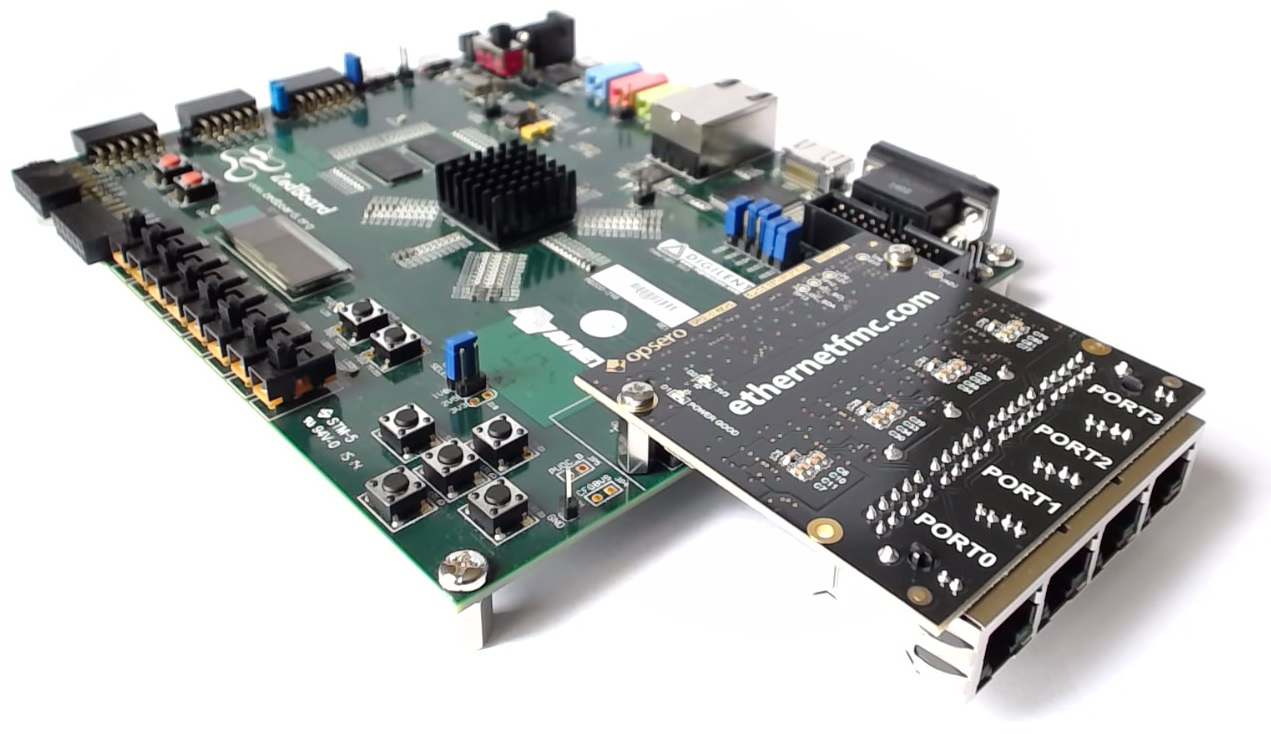
In this two-part tutorial, we’re going to create a multi-port Ethernet design in Vivado 2015.4 using both the GMII-to-RGMII and AXI Ethernet Subsystem IP cores. We’ll then test the design on hardware by running an echo server on lwIP. Our target hardware will be the ZedBoard armed with an Ethernet FMC, which adds 4 additional Gigabit Ethernet ports to our platform. Ports 0 to 2 of the Ethernet FMC will connect to separate AXI Ethernet Subsystem IPs which will be configured in DMA mode. Port 3 of the Ethernet FMC will connect to GEM1 of the Zynq PS through the GMII-to-RGMII IP, while the on-board Ethernet port of the ZedBoard will connect to GEM0.
Requirements
To go through this tutorial, you’ll need the following:
- Vivado 2015.4 (see note below)
- ZedBoard
- Ethernet FMC (standard or robust model will work)
- Platform Cable USB II (or equivalent JTAG programmer)
Note: The tutorial text and screenshots are suitable for Vivado 2015.4 however the sources in the Git repository will be regularly updated to the latest version of Vivado.
Change Vivado’s default language
Before creating our project, we need to make sure that Vivado is configured to use VHDL as it’s default language. We wont be writing any HDL code, however the constraints that we use will be dependent on the project language being set to VHDL, so it’s important that we set this:
- Open Vivado.
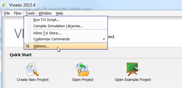
- From the menu, select Tools->Options.
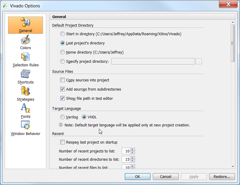
- In the “General” tab select target language : VHDL.
Create a new Vivado project
Follow these steps to create a new project in Vivado:
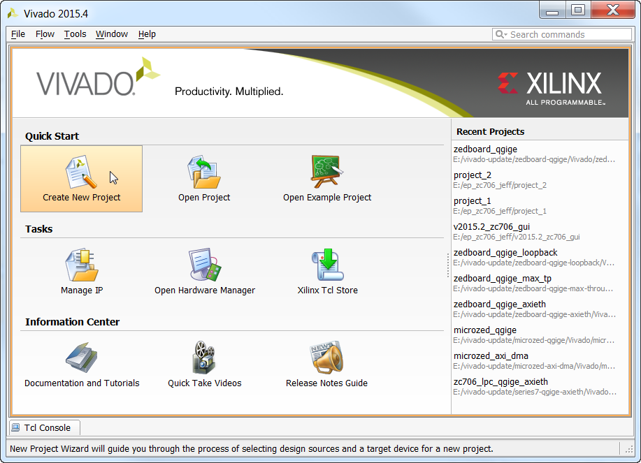
- From the welcome screen, click “Create New Project”.
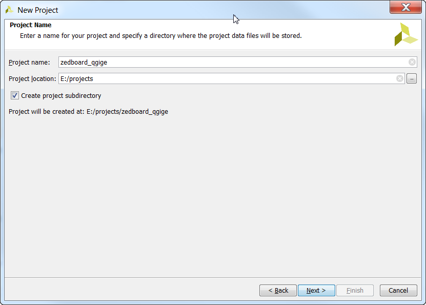
- Specify a folder for the project. I’ve created a folder named “zedboard_qgige”. Click “Next”.
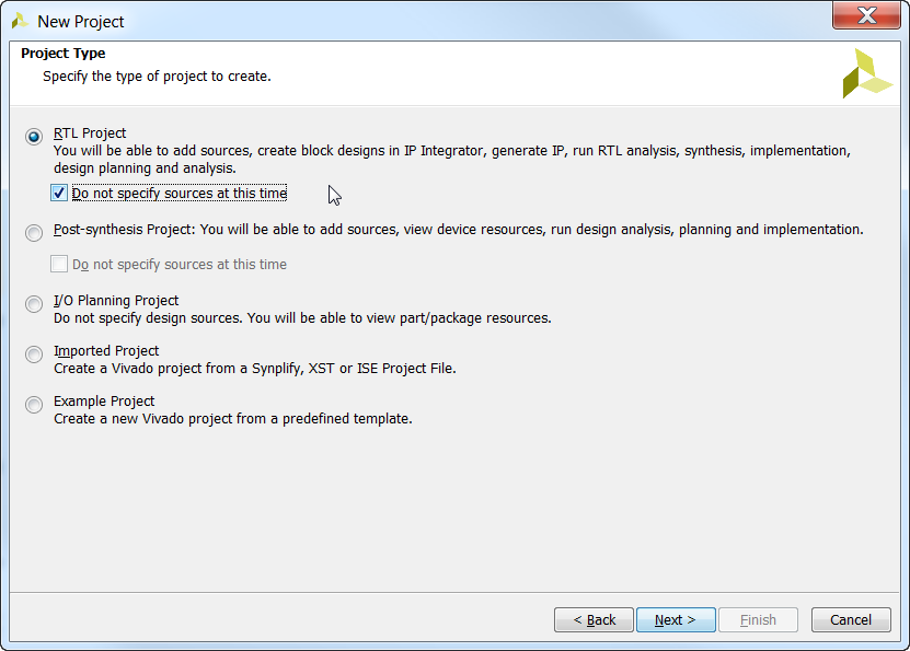
- For the Project Type window, choose “RTL Project” and tick “Do not specify sources at this time”. Click “Next”.
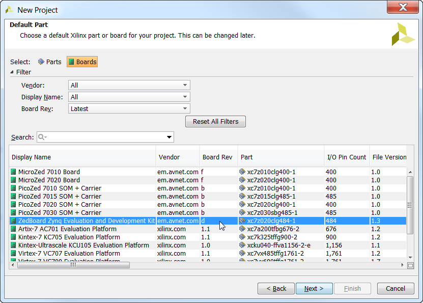
- For the Default Part window, select the “Boards” tab and then select the “ZedBoard Zynq Evaluation and Development Kit” and click “Next”.
- Click “Finish” to complete the new project wizard.
Setup the Zynq PS
We start off the design by adding the Zynq PS (aka. Processor System) and make the connections specified by the ZedBoard board definition file which is included with Vivado 2015.4.
- From the Vivado Flow Navigator, click “Create Block Design”.
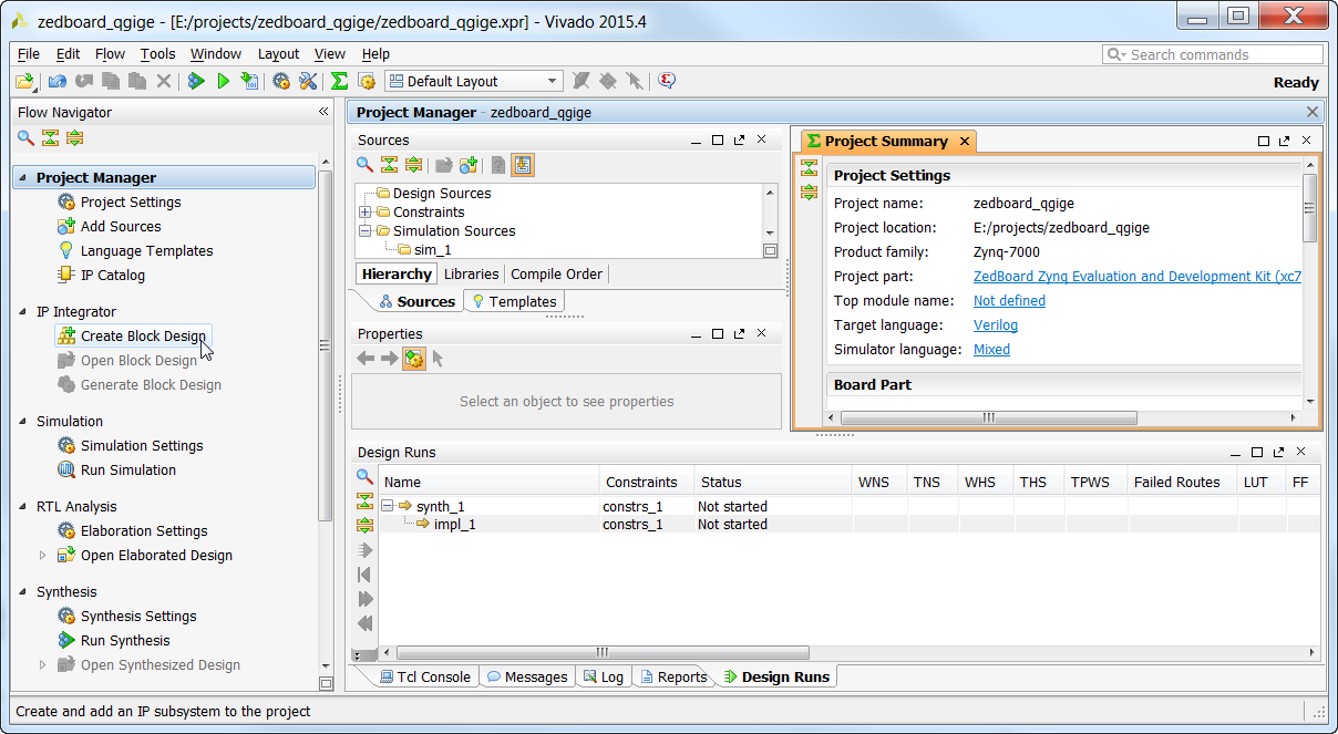
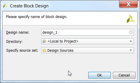
- Specify a name for the block design. Let’s go with the default “design_1” and leave it local to the project. Click “OK”.
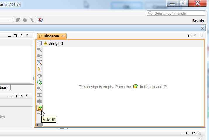
- In the Block Design Diagram, you will see a message that says “This design is empty. Press the (Add IP) button to add IP.”. Click on the “Add IP” icon either in the message, or in the vertical toolbar.
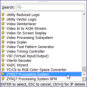
- The IP catalog will appear. Go to the end of the list and double click on “ZYNQ7 Processing System” – it should be the second last on the list.
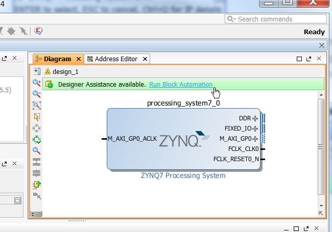
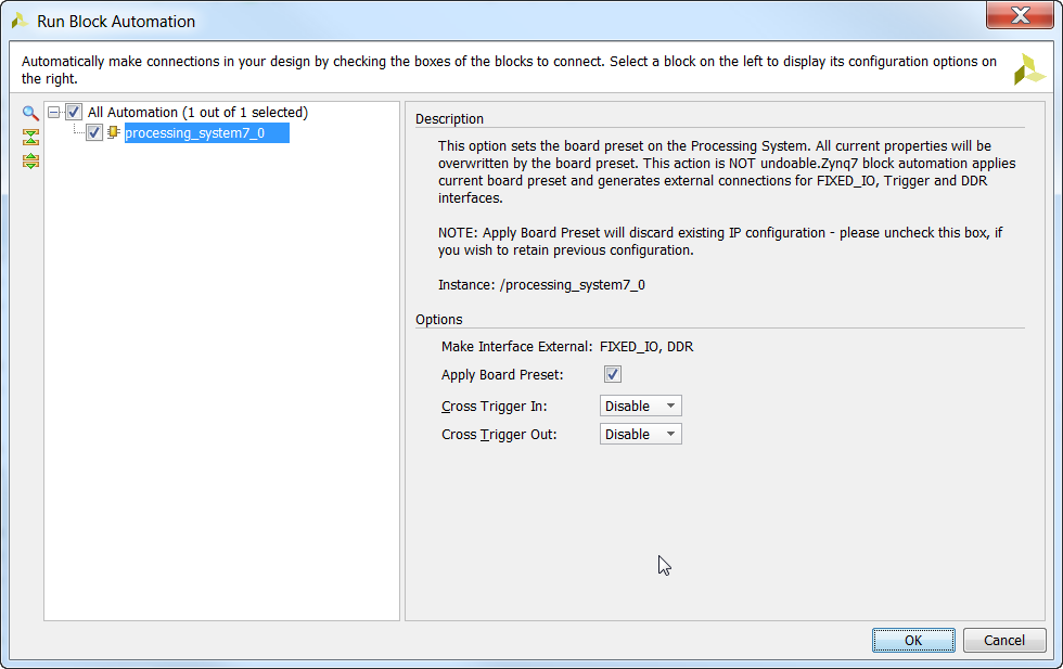
- In the Block Design Diagram, you will see a message that says “Designer Assistance available. Run Block Automation”. Click on the “Run Block Automation” link.
- Block Automation uses the board definition file for the ZedBoard to make connections and pin assignments to external hardware such as the DDR and the on-board Ethernet port. Just make sure that “Apply Board Preset” is ticked and click OK.
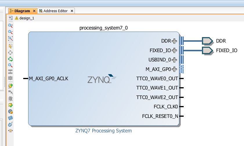
- Now our block diagram has changed and we can see that the DDR and FIXED_IO are connected externally. We can now configure the Zynq PS for our specific needs. Double click on the Zynq PS block to open the Re-customize IP window.
- From the Page Navigator, select “Clock Configuration” and open the “PL Fabric Clocks” tree. Notice that
FCLK_CLK0is enabled by default and set to 100MHz, this will serve as the clock for our AXI interfaces. Now enableFCLK_CLK1andFCLK_CLK2and set them to 125MHz and 200MHz respectively. The FCLK_CLK1 (125MHz) will be needed by the AXI Ethernet Subsystem blocks and it will be used to clock the RGMII interfaces. FCLK_CLK2 (200MHz) will be required by both the GMII-to-RGMII and AXI Ethernet Subsystem IPs and it is needed to clock the IDELAY_CTRLs.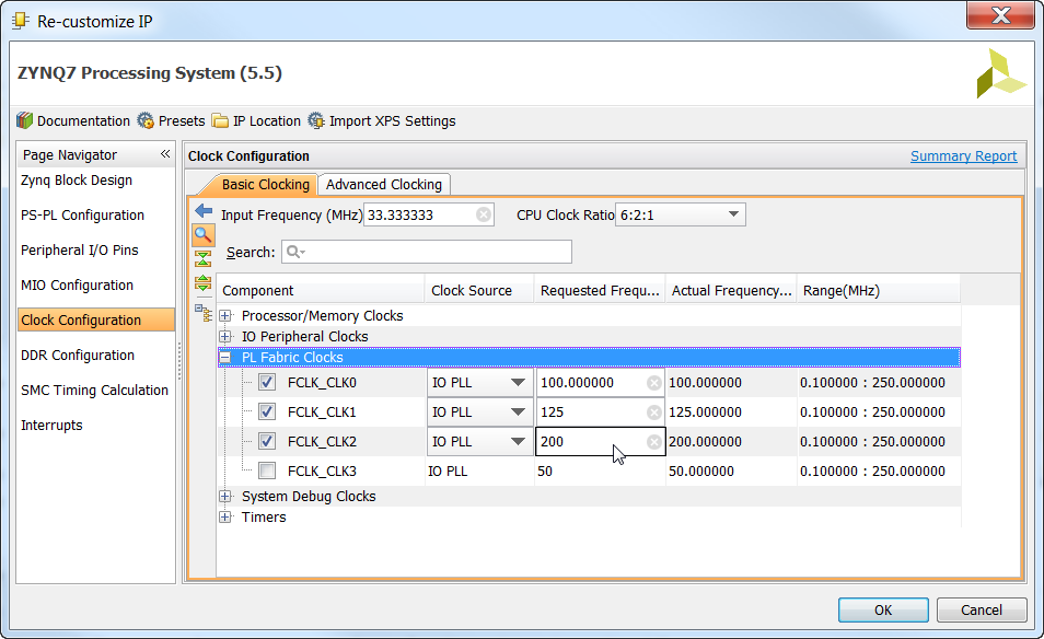
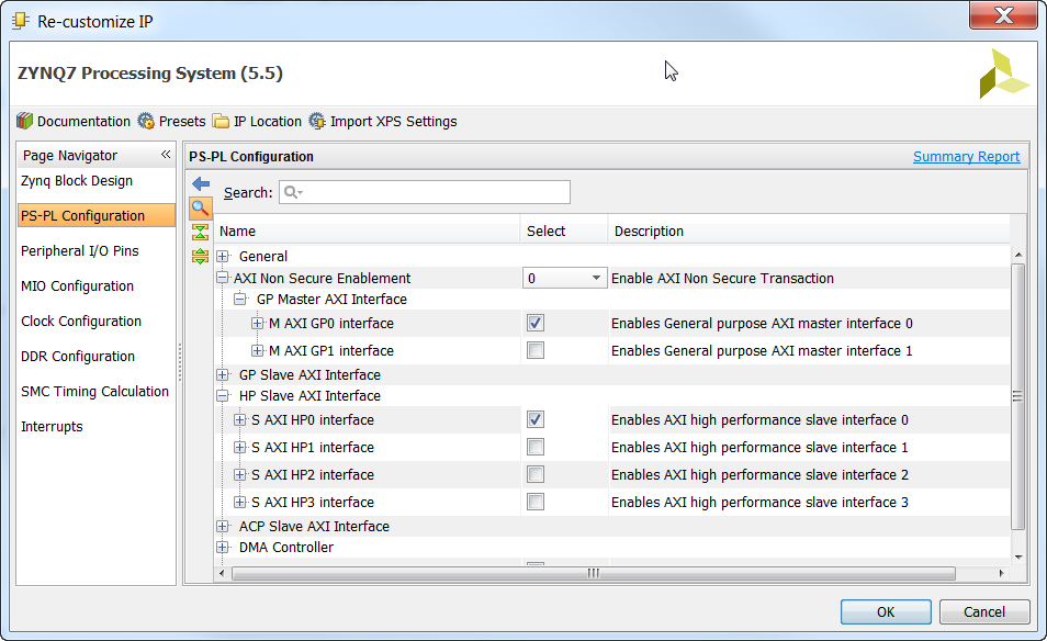
- Now from the Page Navigator, select “PS-PL Configuration”. By default the Master AXI GP0 interface should be enabled as you can see in the image. You must also enable the High Performance Slave AXI HP0 interface as shown. The HP Slave AXI Interface provides a high-bandwidth connection to the DDR3 memory controller - this will be needed by the DMA engines which we will create after we add the AXI Ethernet Subsystem blocks to our design.
- The last thing to do is to enable interrupts. From the Page Navigator, select “Interrupts” and tick to enable “Fabric Interrupts” then
IRQ_F2P[15:0]. Interrupts will be generated by all the Ethernet IPs and by the DMA engine IPs.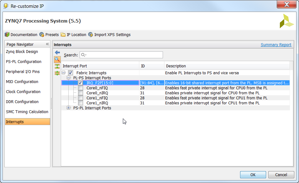
- Now click “OK” to close the Re-customize IP window.
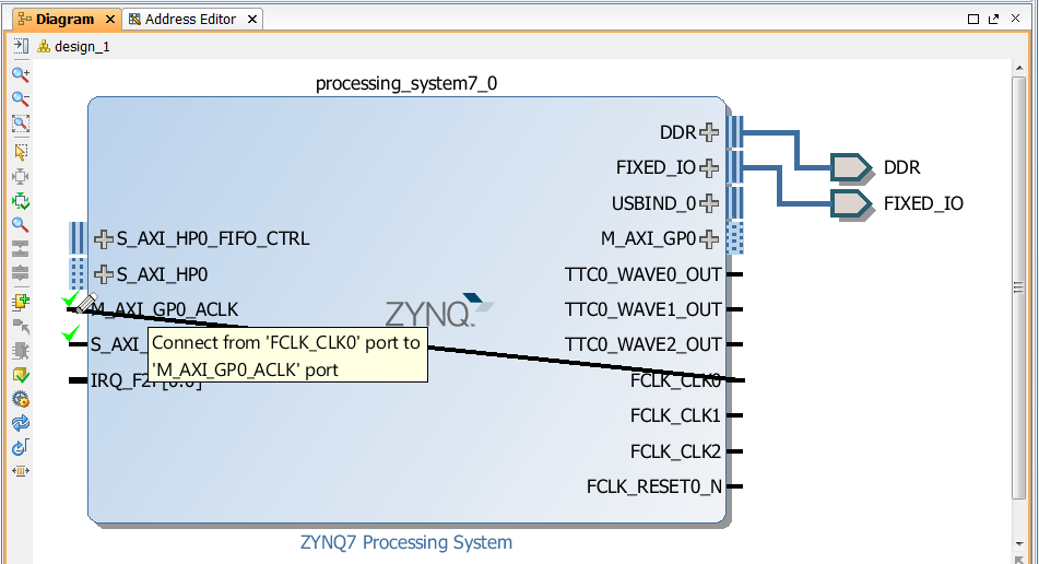
- You will notice that the PS block has gotten a bit bigger and it has more ports. Connect FCLK_CLK0 (100MHz) to the GP Master AXI clock input (M_AXI_GP0_ACLK) by dragging a trace from one pin to the other.
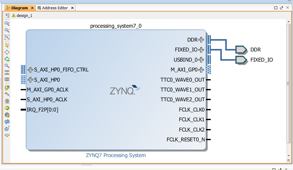 This action will draw a wire between the pins and make the connection.
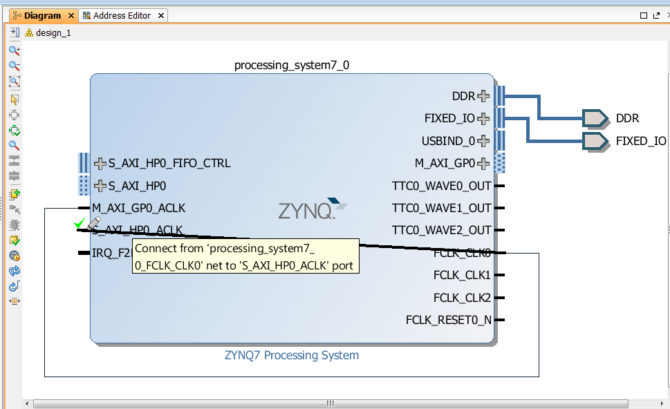
- Also connect the FCLK_CLK0 to the HP Slave AXI Interface clock input (S_AXI_HP0_ACLK).
- Now open the IP Catalog and add 3 x AXI 1G/2.5G Ethernet Subsystem IPs to the design (you will have to add one at a time). Once you have done this, you should have three AXI Ethernet Subsystem blocks in your design:
axi_ethernet_0,axi_ethernet_1andaxi_ethernet_2.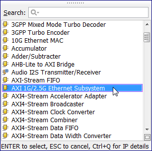
- To wire the AXI Ethernet Subsystem blocks in DMA mode, we’ll use the block automation feature, however before running this, we want to configure the “shared logic” option of the cores first. The AXI Ethernet Subsystem IP is designed with the option to include “shared logic” in the core. The shared logic includes an IDELAY_CTRL to control the IODELAYs on the RGMII interface, as well as an MMCM to generate a 90 degree skewed clock for generation of the RGMII TX clock. When we use multiple AXI Ethernet Subsystem blocks in the one design, we can save on resources by having only one of those cores include the “shared logic”. The core containing the “shared logic” will naturally share the IDELAY_CTRL with the other cores, and it will have outputs for the clocks generated by the MMCM so that it can share them too. Let’s make
axi_ethernet_0be the one that contains the shared logic, so double click on it to bring up the Re-customize IP window.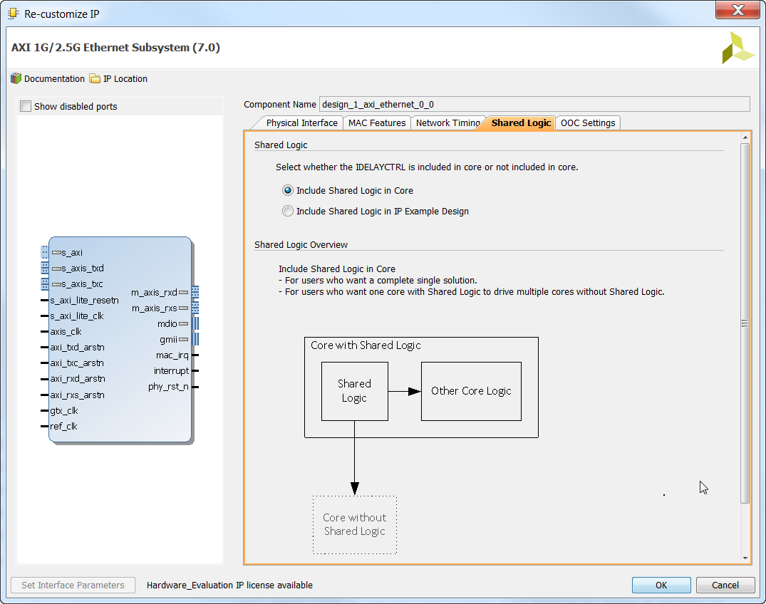
- Go to the “Shared Logic” tab (don’t worry about any of the other options for now). Select the “Include Shared Logic in Core” option and click OK.
- Now open the Re-customize IP window for
axi_ethernet_1, go to the “Shared Logic” tab and select the “Include Shared Logic in IP Example Design” option and click OK. Do the same foraxi_ethernet_2.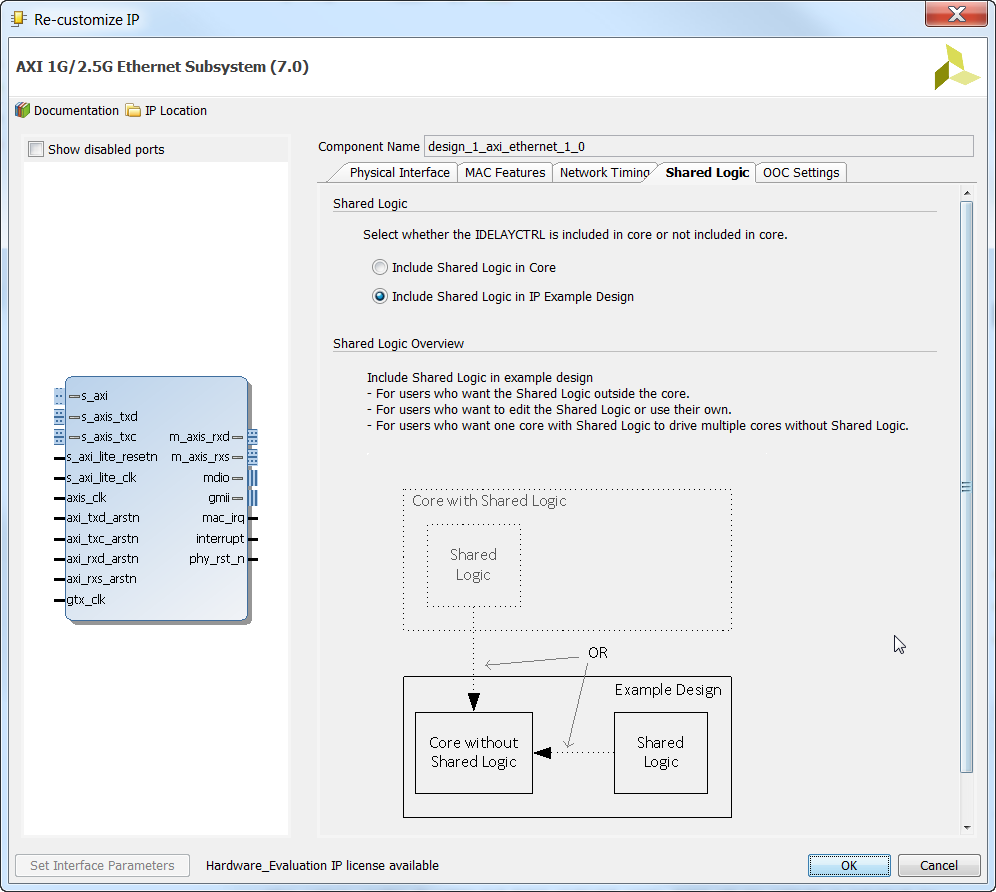
- Now we can wire up the Ethernet blocks by using the block automation feature. Notice there is a message in your block diagram saying “Designer Assistance available. Run Block Automation”. Click on the “Run Block Automation” link.
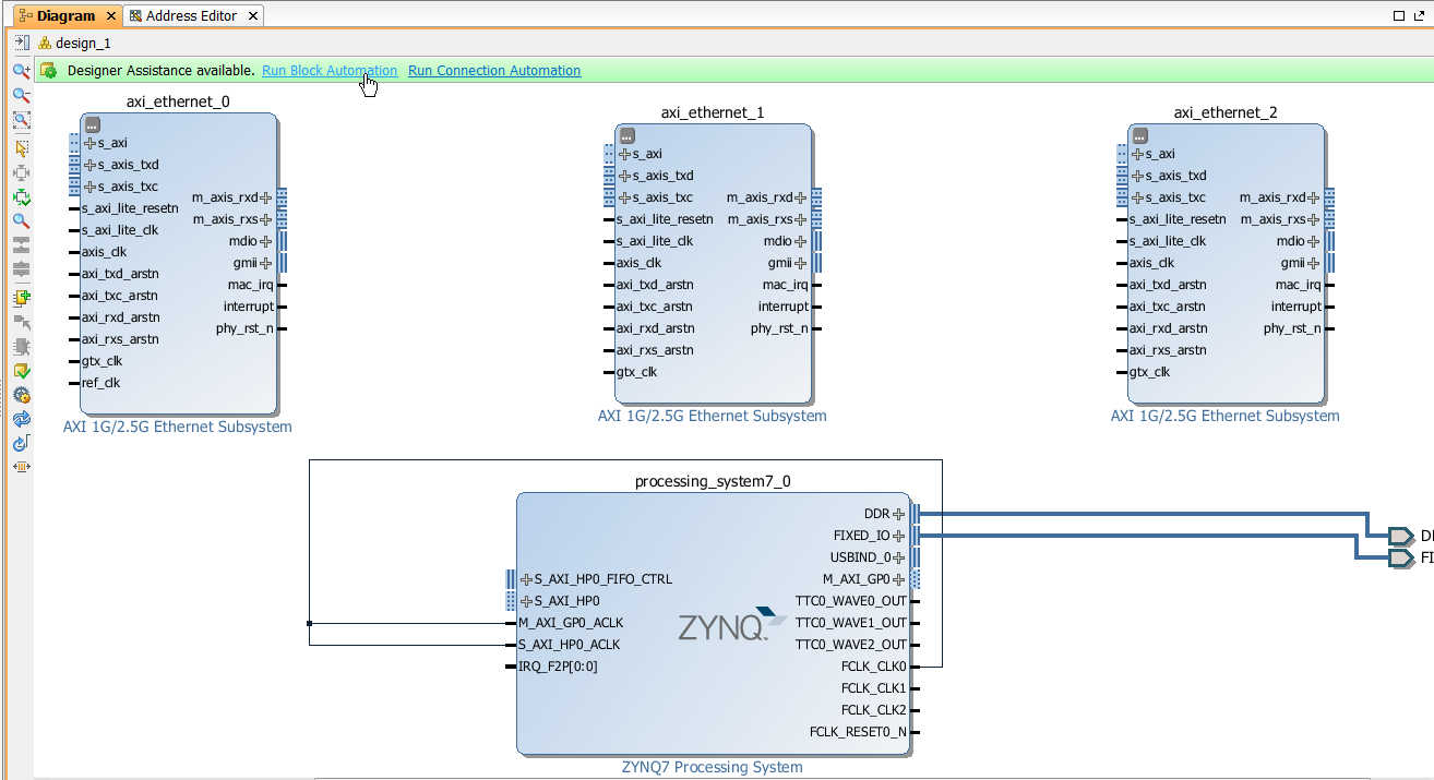
- In the “Run Block Automation” window, you will have automation options for each of the Ethernet blocks. Tick to enable all of them, then select them one by one and make sure that they are each configured for an “RGMII” physical interface and a “DMA” connection to the AXI Streaming Interfaces. By default they will all be configured for GMII so it is important to set the physical interface correctly here and for each one of them. Then click OK.
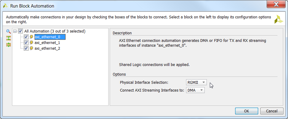
- After the block automation has run its course, you will notice that it has added a Clocking Wizard block called
axi_ethernet_0_refclk. This block generates a 125MHz and 200MHz clock to feed the Ethernet blocks, however we will be using the Zynq PS to generate those clocks, so we don’t need this block. Click once on theaxi_ethernet_0_refclkblock and press Delete to remove it from the block diagram.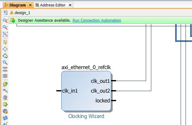
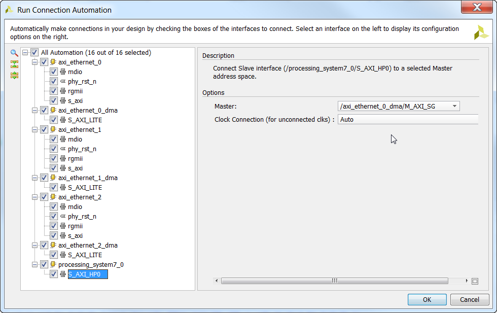
- We can now use the Connection Automation feature to wire up our AXI interfaces. Click “Run Connection Automation” from the block diagram.
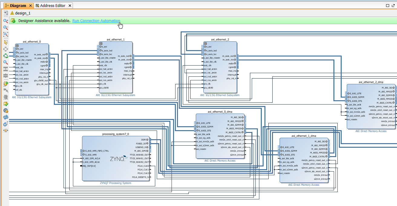
- Like before, tick to enable ALL of the connections. We then we need to select each of the interfaces one-by-one and choose the right settings. Luckily the defaults are good for us in Vivado 2015.4, but check the screenshots below if you are using a different version. Then click OK.
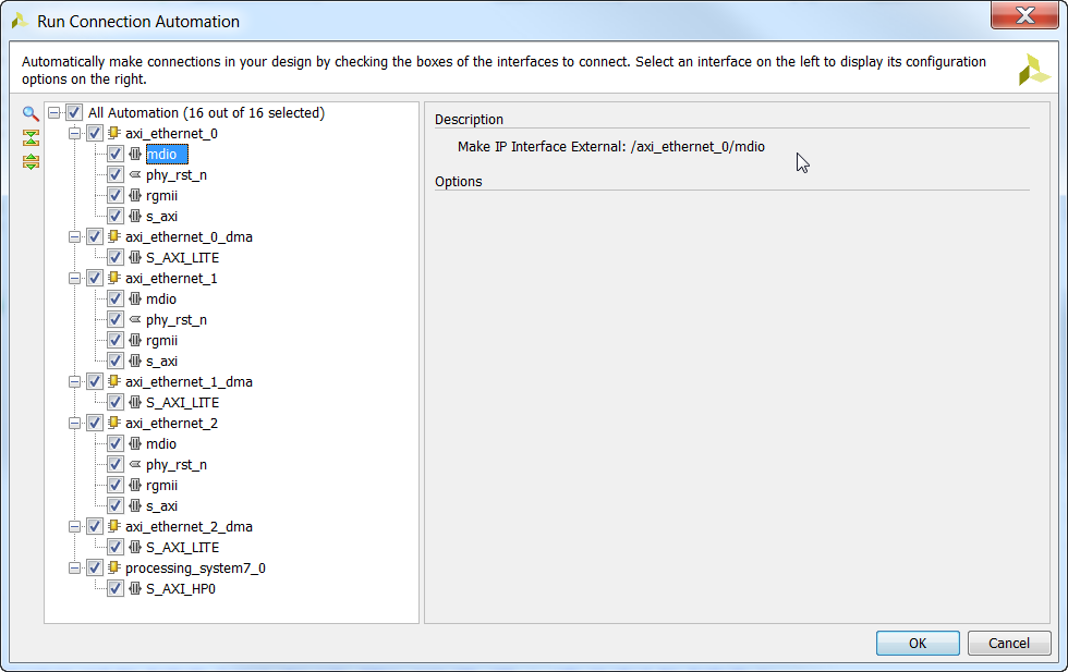
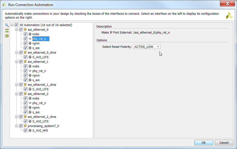
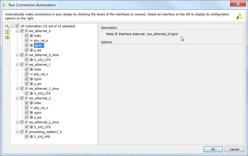
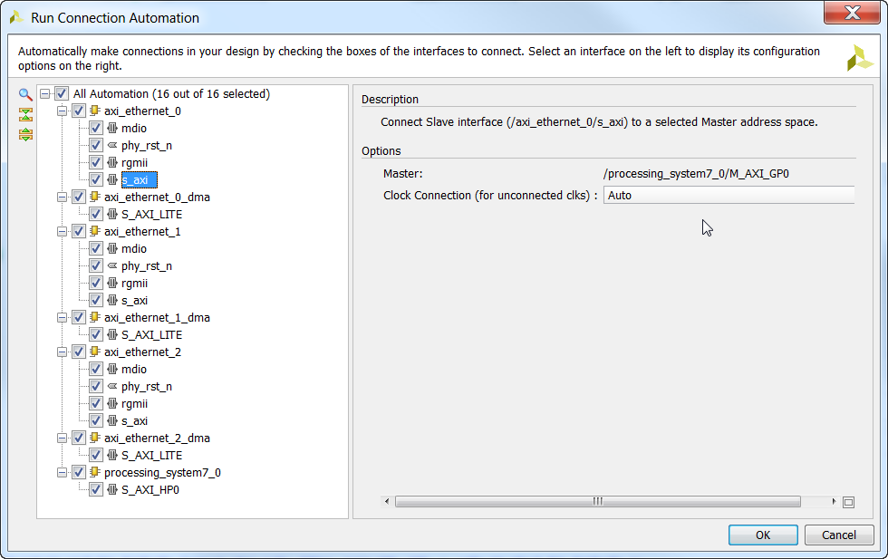
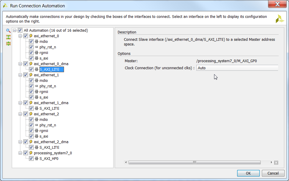
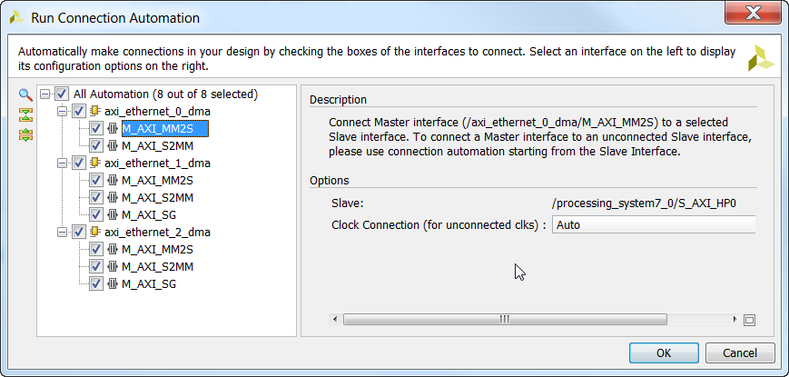
- When the automation feature has run its course, you will notice that again you have the option to “Run Connection Automation”. Maybe this will not be the case in future versions of Vivado, but it is the case for 2015.4. So again click “Run Connection Automation”, tick to enable all the interfaces for automation and make sure the settings are correct (defaults are good for 2015.4). They should all be configured to connect to the HP Slave AXI Interface (S_AXI_HP0) and use the “Auto” clock connection.
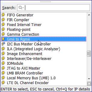
- Now it’s time to add the GMII-to-RGMII block for Port 3 of the Ethernet FMC. Open the IP Catalog and double click on “Gmii to Rgmii”.
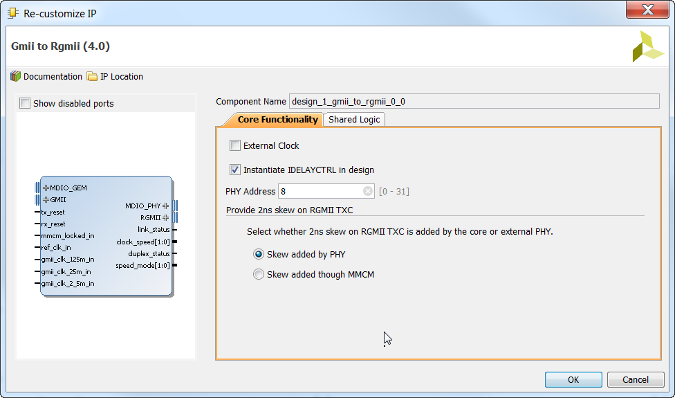
- Double click on the GMII-to-RGMII block to open the Re-customize IP window.
- In the “Core Functionality” tab, tick “Instantiate IDELAYCTRL in design”, set the PHY Address to 8 and select the option “Skew added by PHY”. Notice that the GMII-to-RGMII core has an MDIO input and an MDIO output. Why does the MDIO bus have to pass through the core? That’s because the GMII-to-RGMII core has logic that sits on the MDIO bus to receive commands from the MAC for configuration. The PHY address we specify here allows us to give the core a unique address on the MDIO bus, and it is very important that the address be different to that of the external PHY. On the Ethernet FMC, all the PHYs are configured with address 0, so we can give the GMII-to-RGMII core an address of 8 without creating a bus conflict. As for the “Skew added by the PHY” option, this concerns the RGMII transmit clock. Some PHYs, including the 88E1510 on the Ethernet FMC, have a feature to add a delay to the incoming RGMII TX clock so that it aligns well for sampling the incoming RGMII transmit data. The GMII-to-RGMII core allows us to specify where the skew is added: in the PHY or in the FPGA fabric (MMCM). The skew should be added by one or the other, never both, or the clock will be poorly aligned for sampling the data and the RGMII interface will fail.
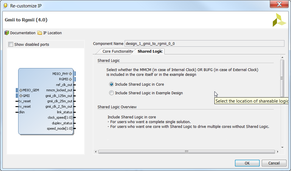
- Now open the “Shared Logic” tab and select “Include Shared Logic in Core”.
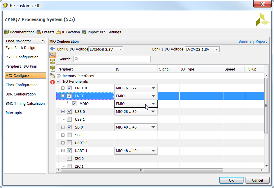
- To connect the GMII-to-RGMII core to the PS, we need to enable GEM1 in the PS. Double click on the Zynq PS block and select “MIO Configuration” in the Page Navigator. Tick to enable “ENET 1” and select “EMIO” (Extended Multiplexed Input/Output). Selecting EMIO allows us to route GEM1 through to the FPGA fabric, so that we can then connect it to our GMII-to-RGMII core and then out to the Ethernet FMC.
- Now you should see two extra ports on the Zynq PS block:
GMII_ETHERNET_1andMDIO_ETHERNET_1. Make a connection betweenMDIO_GEMof the GMII-to-RGMII block andMDIO_ETHERNET_1of the Zynq PS.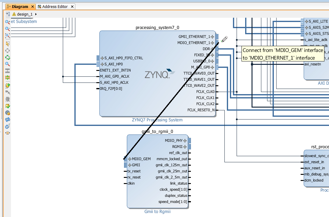
- Now make a connection between “GMII” of the GMII-to-RGMII block and
GMII_ETHERNET_1of the Zynq PS.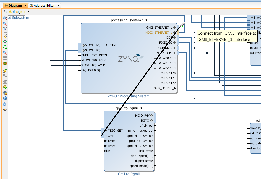
- Now we need to make the
MDIO_PHYand “RGMII” ports external so that they can connect to the Ethernet FMC. Right click on each of these interfaces and select “Make External”.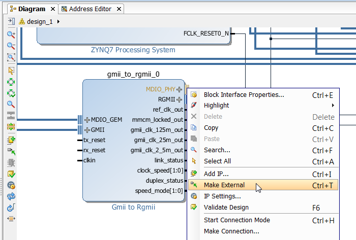
- Now find the external ports on the right hand side of the block diagram. We’ll need to rename them so that the names fit with the constraints that we will later add to the project. Click first on the
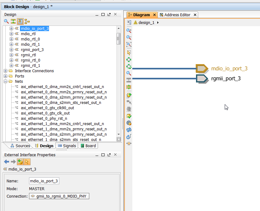
MDIO_PHYport and rename itmdio_io_port_3. Then click on the “RGMII” port and rename itrgmii_port_3. The port name can be changed in the “External Interface Properties” window that normally sits just below the “Design” window and to the left of the block diagram (see image below).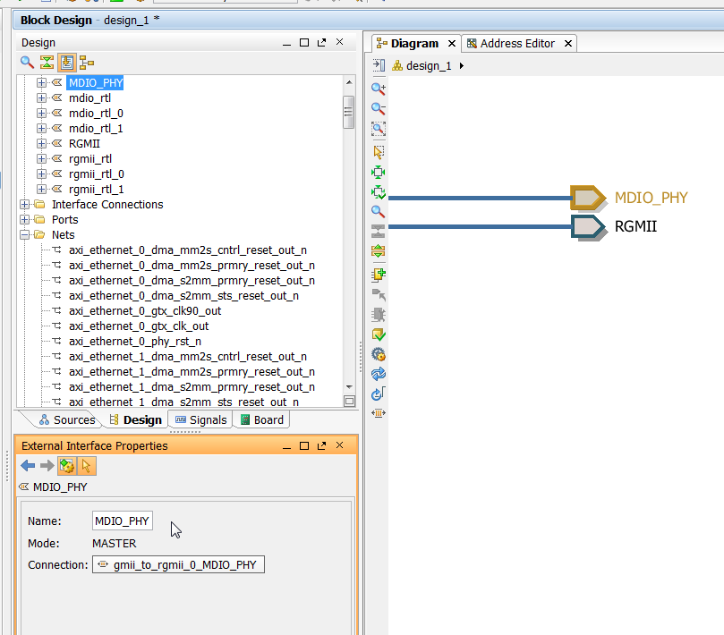
- Once you have changed the names, your ports should now look like this.
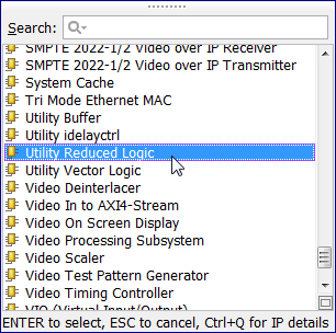
- The GMII-to-RGMII block doesn’t provide us with a reset signal for the PHY, so we have to add some logic to provide that signal. Open the IP Catalog and add a “Utility Reduced Logic” IP.
- Double click on the
util_reduced_logic_0block and set the “C Size” to 1 and the “C Operation” to “and”. Then click OK.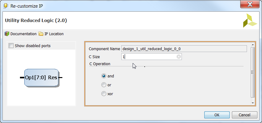
- Now connect the input of the
util_reduced_logic_0block to the active-low peripheral reset output of the Processor System Reset block.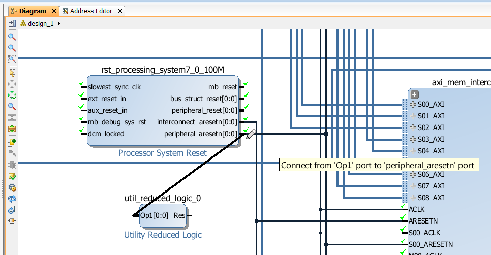
- Now right click on the output of the
util_reduced_logic_0block and select “Make External”.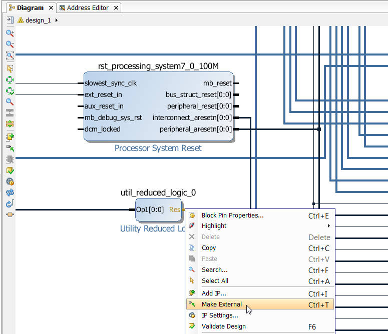
- The external port will have been named “Res” by default. Change this name to
reset_port_3so that it matches the constraints we will later add to the project. - The MDIO, RGMII and reset ports of the 3 x AXI Ethernet Subsystem blocks will have already been externalized during the automation process, however they will have been given odd names so we need to change those names to match the constraints that we will later add to the project. Go through the ports one-by-one and rename them as follows:
- axi_ethernet_0 should have its external ports named
mdio_io_port_0,rgmii_port_0andreset_port_0. - axi_ethernet_1 should have its external ports named
mdio_io_port_1,rgmii_port_1andreset_port_1. - axi_ethernet_2 should have its external ports named
mdio_io_port_2,rgmii_port_2andreset_port_2.
- axi_ethernet_0 should have its external ports named
- Now open the IP Catalog and add a Concat (concatenate) IP to the design. The concatenate IP takes a series of single inputs and concatenates them into a vector output. We will need this IP to be able to connect all the interrupts to the
IRQ_F2P[0:0]vector input of the PS.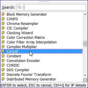
- Double click on the Concat block and set the number of ports to 12. Then click OK.
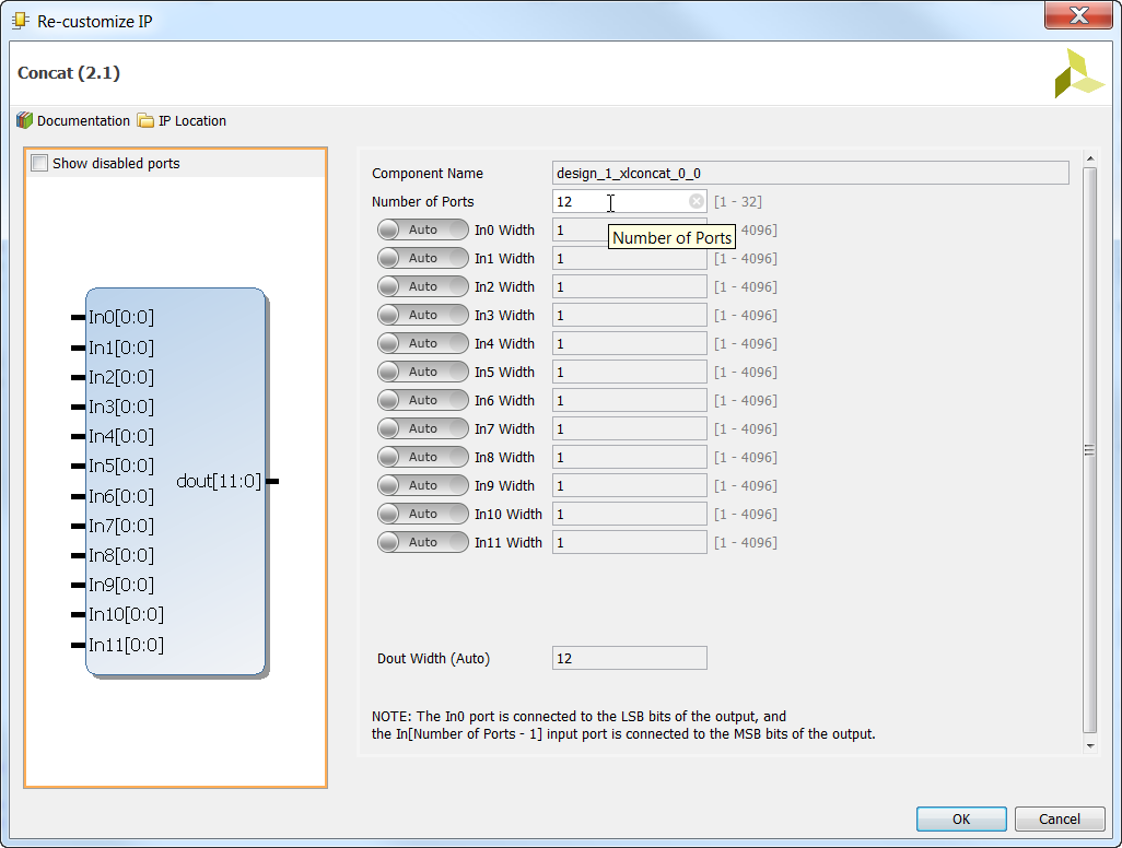
- Now we must connect all the interrupts to the Concat IP. One-by-one, go through and make all the following connections. Note that the order of pin assignment is not important because it will all be transferred to the SDK in the hardware description and be correctly mapped by the BSP.
- Connect axi_ethernet_0_dma/mm2s_introut to xlconcat_0/In0
- Connect axi_ethernet_0_dma/s2mm_introut to xlconcat_0/In1
- Connect axi_ethernet_1_dma/mm2s_introut to xlconcat_0/In2
- Connect axi_ethernet_1_dma/s2mm_introut to xlconcat_0/In3
- Connect axi_ethernet_2_dma/mm2s_introut to xlconcat_0/In4
- Connect axi_ethernet_2_dma/s2mm_introut to xlconcat_0/In5
- Connect axi_ethernet_0/mac_irq to xlconcat_0/In6
- Connect axi_ethernet_0/interrupt to xlconcat_0/In7
- Connect axi_ethernet_1/mac_irq to xlconcat_0/In8
- Connect axi_ethernet_1/interrupt to xlconcat_0/In9
- Connect axi_ethernet_2/mac_irq to xlconcat_0/In10
- Connect axi_ethernet_2/interrupt to xlconcat_0/In11
- Now connect the Concat output to the IRQ_F2P input of the Zynq PS.
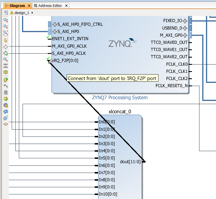
- Now let’s connect FCLK_CLK2, the 200MHz clock, to the Ethernet blocks. First connect
FCLK_CLK2to theref_clkpin ofaxi_ethernet_0.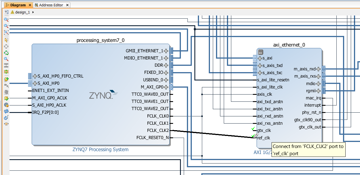
- Then connect FCLK_CLK2 to the “clkin” pin of the GMII-to-RGMII block. Now for those who are curious, you probably noticed that the GMII-to-RGMII block only has one clock input (clkin). This input must be connected to 200MHz which will be used to clock the IDELAY_CTRL, but also it will be used to generate three other clocks: 125MHz, 25MHz and 2.5MHz which are used for link speeds 1Gbps, 100Mbps, 10Mbps respectively. The actual link speed is determined by the PHY during the autonegotiation process and it is up to the processor to read the link speed from the PHY and then pass this value onto the GMII-to-RGMII core so that it uses the appropriate clock. By default, it is set to use the 2.5MHz clock for a link speed of 10Mbps.
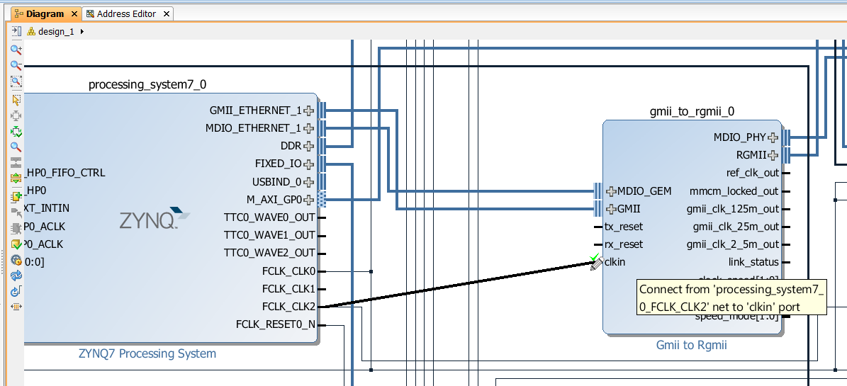
- Now let’s connect the
tx_resetandrx_resetports to the peripheral reset signal. Remember to connect BOTH of them (one at a time).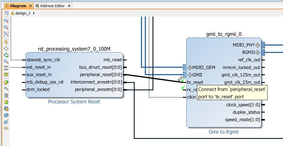
- Now we need to connect the 125MHz clock to the
gtx_clkport of the AXI Ethernet Subsystem blockaxi_ethernet_0(the one containing the shared logic). We did enable FCLK_CLK1 for this purpose, and you can make that connection if you wish, but for this tutorial we will explore another possibility. The Ethernet FMC has an on-board 125MHz oscillator which can also be used to supplygtx_clk. In order to use it, we just need to add a differential buffer to our design. Open the IP Catalog and add a “Utility Buffer” to the design.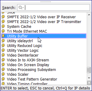
- Connect the output of the buffer to the
gtx_clkinput ofaxi_ethernet_0.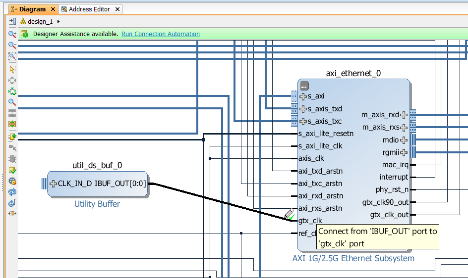
- Now click on the plus (+) symbol on the input of the buffer to show the differential inputs.
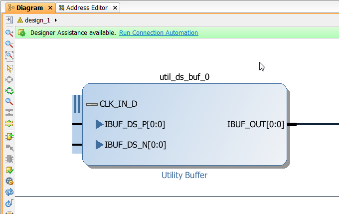
- Now right-click on each of the individual inputs of the buffer and select “Make External”. You should end up with two external input ports named
IBUF_DS_P[0:0]andIBUF_DS_N[0:0].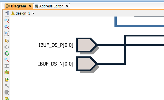
- Rename those external input ports to
ref_clk_pandref_clk_nrespectively.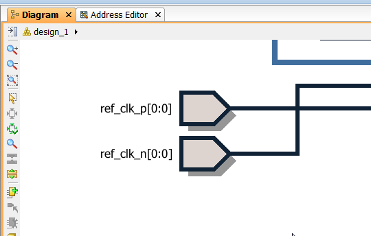
- Now there is only one more thing to add. The Ethernet FMC has two inputs that are used to enable the on-board 125MHz oscillator and to select it’s frequency (it can alternatively be set to 250MHz). We need to add some constants to our design to enable the oscillator and to set it’s output frequency to 125MHz. Open the IP Catalog and add two Constant IPs.
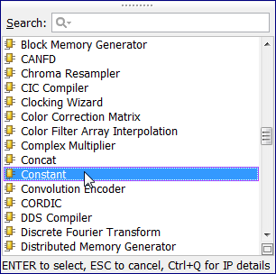
- By default, they will be set to constant outputs of 1, which is exactly what we need. So all we must do is make their outputs external and rename them to
ref_clk_oeandref_clk_fsel. The result should be as shown in the image below.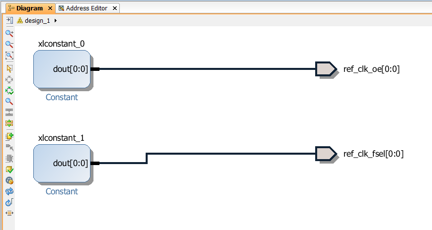
- Save the block diagram by clicking “File->Save Block Design”.
Create the HDL wrapper
Our Vivado block diagram is complete and we now need to create a HDL wrapper for the design.
- Open the “Sources” tab from the Block Design window.
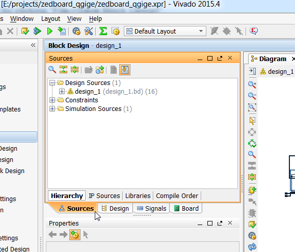
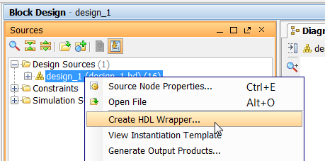
- Right-click on “design_1” and select “Create HDL wrapper” from the drop-down menu.
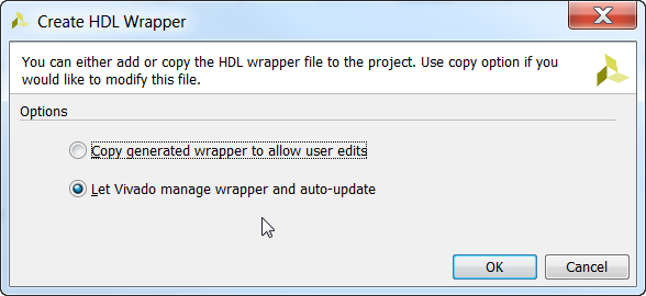
- From the “Create HDL wrapper” window, select “Let Vivado manage wrapper and auto-update”. Click “OK”.
Add the constraints file
The last thing we need to add to our project will be the constraints. The constraints file contains:
- Pin assignments for all the external ports of our block design, which in our case are the pins that are routed to the FMC connector and through to our Ethernet FMC
- A definition for the 125MHz reference clock that comes in from the Ethernet FMC
- IODELAY grouping constraints to assign each port to one of two groups corresponding to the I/O bank that it occupies. We don’t want the tools trying to group all the ports to the same IDELAY_CTRL, but rather there should be one instantiated for each I/O bank - in our case, there is one instantiated in the
axi_ethernet_0and another ingmii_to_rgmii_0.
Follow these steps to add the constraints file to your project:
- Download the constraints file from this link: Constraints for ZedBoard and Ethernet FMC using GMII-to-RGMII and AXI Ethernet
- Save the constraints file somewhere on your hard disk.
- From the Project Manager, click “Add Sources”.
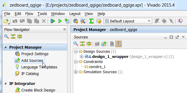
- Then click “Add or create constraints”.
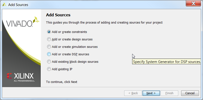
- Then click “Add files” and browse to the constraints file that you downloaded earlier.
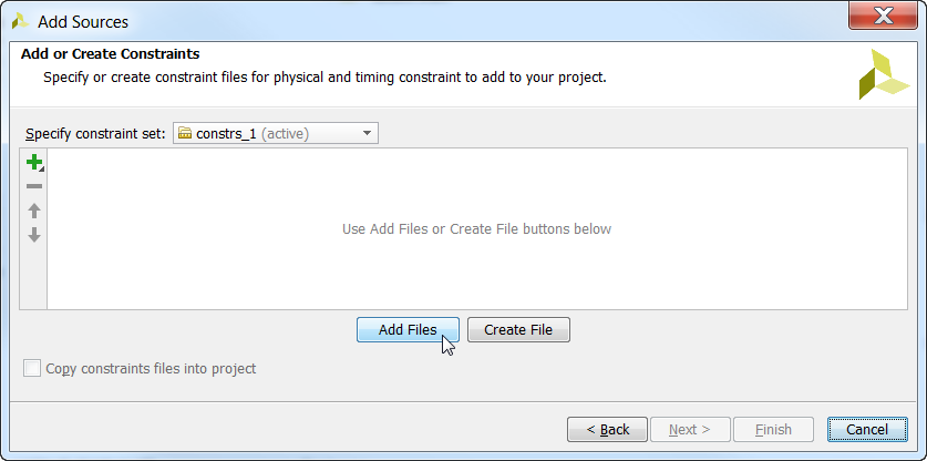
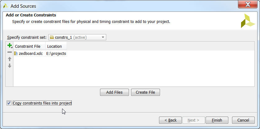
- Tick “Copy constraints files into project” and click Finish.
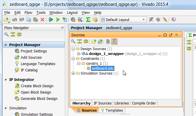
- You should now see the constraints file in the Sources window.
Sources Git repository
Sources for re-generating this project automatically can be found on Github at the links below. There is a version of the project for the ZedBoard and the MicroZed. There is also a version that uses only the AXI Ethernet Subsystem IP.
- ZedBoard using GMII-to-RGMII and AXI Ethernet Subsystem
- ZedBoard using AXI Ethernet Subsystem only
- MicroZed using GMII-to-RGMII and AXI Ethernet Subsystem
Instructions for re-generating those projects can be found in this post: Version control for Vivado projects. We will also discuss that in the following tutorial, as well as testing the projects on actual hardware.
Testing the project on hardware
In the second part of this tutorial we will generate the bitstream for this project, export it to the SDK and then test an echo server application on the hardware. The echo server application runs on lwIP (light-weight IP), the open source TCP/IP stack for embedded systems.
Alternatively, you might be interested in learning how to use this design to bring up 4 extra Ethernet ports in PetaLinux.
If you have any questions about this tutorial, or if you run into problems, please leave me a comment below.