Title here
Summary here
Running multi-camera YOLOv5 on Zynq UltraScale+ using a Hailo-8 AI accelerator via FPGA Drive FMC
February 15, 202419 minutes

Over the last few months I’ve been lucky to work with two very talented people on an interesting project for multi-camera machine vision applications: Gianluca Filippini and Mario Bergeron. Back in 2022, I was contacted by Gianluca, an engineer from EBV Elektronik. He was using our FPGA Drive FMC, an adapter for connecting Solid-state drives to FPGAs - but he wasn’t interested in SSDs. He wanted to use it for a new and exciting AI accelerator from a company called Hailo. The idea was to take the Zynq UltraScale+, a powerful MPSoC geared for video applications, and arm it with a top performing AI accelerator to run intelligent vision algorithms on the edge.
It made a lot of sense. If you’ve had any experience with the AMD Xilinx Deep Learning Processor Unit (DPU), then you know about the challenges of putting a neural network in the FPGA. If you haven’t used the DPU then let me spoil the punchline: The DPU consumes a tonne of FPGA resources and the performance is a little disappointing. With the current solutions on offer, it seems that implementing a neural network in the FPGA fabric is not the way to get the most bang for your buck. A better solution is to externalize the neural network and reserve the valuable FPGA resources for something it does spectacularly: image processing. The Hailo-8 is a perfect fit; an external AI accelerator with a high-throughput PCIe interface that runs AI models way faster than any FPGA-based solution, while also being more power efficient.
Months passed. I launched the RPi Camera FMC and Gianluca contacted me again. This time he wanted to run YOLOv5 on 4x Raspberry Pi cameras simultaneously, accelerated by the Hailo-8. This sounded like fun, so I had to get involved. Over the next few months we worked between continents to build the demo that I’ll be describing in this post. We teamed up with embedded vision and machine learning expert Mario Bergeron, who was already working on pairing the Hailo-8 with the ZUBoard. I learned heaps and had a lot of fun working with these guys. In the end, I hope we’ve created not only a great demo, but also a useful reference platform for others who want to build similar systems. In this post I’m providing a detailed description of the design and instructions for building and running it. I’ve also described any hurdles that we went through, and any lessons learned.
The architecture of this system involves the following main elements:
The block diagram below illustrates the key elements of this design and their interconnections.
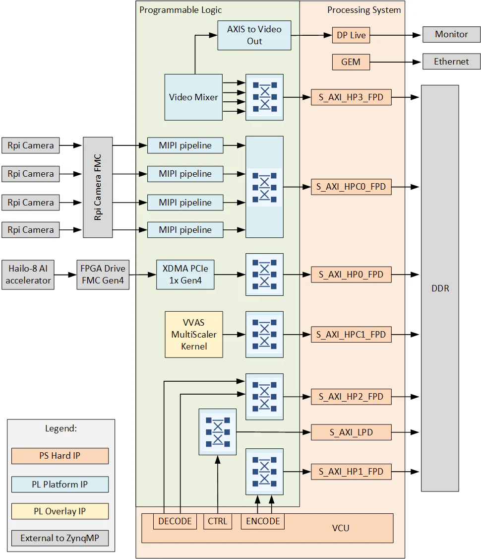
There are four main capture/input pipelines in this design, one for each of the 4x Raspberry Pi cameras. Note that it is also possible to connect USB cameras and/or IP cameras to this design, but I’ll leave that for another post. The capture pipelines are composed of the following IP, implemented in the PL of the Zynq UltraScale+:
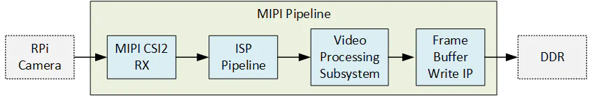
The MIPI CSI-2 RX IP is the front of the pipeline and receives image frames from the Raspberry Pi camera over the 2-lane MIPI interface. The MIPI IP generates an AXI-Streaming output of the frames in RAW10 format. The ISP Pipeline IP performs BPC (Bad Pixel Correction), gain control, demosaicing and auto white balance, to output the image frames in RGB888 format. The Video Processing Subsystem IP performs scaling and color space conversion (when needed). The Frame Buffer Write IP then writes the frame data to memory (DDR). The image below illustrates the MIPI pipeline.
The display pipeline reads frames from memory (DDR) and sends them to the monitor. As this is a multi-camera design, and we would like to display all four video streams on the monitor at the same time, the display pipeline needs to have the ability to combine the four video streams into one. To achieve this, we used the Video Mixer IP with four overlay inputs configured as memory mapped AXI4 interfaces - this allows the mixer to read the four video streams from memory. The Video Mixer requires you to select a single video format for each input layer, which in this design we selected YUY2 (to this Video Mixer this is YUYV8) . This is the video format that was used to train the AI model, and by selecting it here we avoid having to add an extra format conversion to the pipeline. The output of the mixer is set to an AXI-Streaming video interface with YUV 422 format, which is what the DisplayPort live interface wants to see.
The AXIS Subset Converter takes the 3-byte output of the Video Mixer and removes the MSB to produce a 2-byte output which is fed to the AXIS to Video Out Converter. The video output is then fed to the DisplayPort live interface of the Zynq UltraScale+ which is then routed to the monitor.
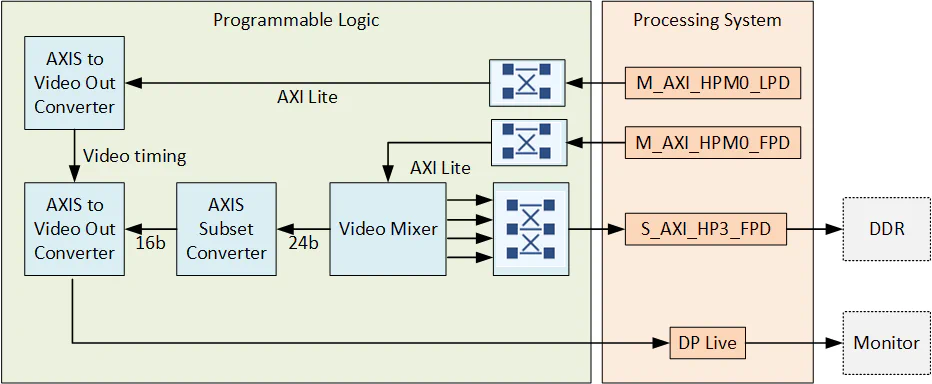
You might be interested to know that before using this display pipeline, we started this design using a different one. The original display pipeline used the VVAS Multi-scaler kernel to combine the four video streams into one. This was done with the vvas-xcompositor GStreamer plugin. The Multi-scaler kernel would read the four 720p video streams from memory. It would combine the four video streams into a single 2K video (in the FPGA fabric) and then write that 2K video back to memory. The combined video would then be read back from memory by the hardened DisplayPort interface module and sent to the monitor. This display pipeline worked well, but it turned out to be a bottleneck on performance due to the extra load it created on the DDR interface. By switching to the Video Mixer based pipeline (shown above), we are no longer writing the combined 2K video to memory and reading it back for display. Instead, the combined video is kept in the FPGA fabric all the way to the DisplayPort live interface.
We also added the VVAS Multi-scaler kernel to this design as a Vitis overlay. The kernel enables hardware accelerated resizing, color space conversion, combining of video frames and more. The accelerator can be exploited through a set of GStreamer plug-ins that you can access in PetaLinux through the installed VVAS packages.
Based on our experience with GStreamer on the Zynq UltraScale+, at any substantial resolution and frame rate, it is essential to use hardware acceleration to perform all resizing, color conversions and any other image processing. That is to say, the APU (processor) of the Zynq UltraScale+ generally does not perform well when it is used to do any of this kind of image processing at a useful frame rate and resolution. To make this clear, let me share numbers from some of the benchmarking done by Mario Bergeron:
| Operation | Input video | Output video | Frame rate |
|---|---|---|---|
| None (baseline) | 720p YUV | 720p YUY | 31.5 fps |
| Scaling | 720p YUV | 1080p YUY | 0.78 fps |
| Scaling + CSC | 720p YUV | 1080p RGB | 0.51 fps |
| Operation | Input video | Output video | Frame rate |
|---|---|---|---|
| None (baseline) | 720p YUV | 720p YUY | 30.2 fps |
| Scaling | 720p YUV | 1080p YUY | 28.9 fps |
| Scaling + CSC | 720p YUV | 1080p RGB | 28.3 fps |
When the CPU performs the scaling and color space conversion, we see a huge drop in performance. If we were to look at the CPU usage for those cases, we would see close to 100% on all cores. When instead the scaling and color space conversion is hardware accelerated with VVAS, we see that frame rates only slightly drop - and if we configured the kernel for a higher throughput (PPC) I’m confident that we wouldn’t see any drop for those operations at those frame rates and resolutions.
To make this a truly powerful reference platform, we included the VVAS Multi-scaler kernel into this design, even though it is not used by the actual Hailo-8 demo script. I’ll include some demo scripts to exploit the VVAS accelerator at a later time.
The Zynq UltraScale+ contains a hardened Video Codec Unit (VCU) that can be used to perform video encoding and decoding of multiple video standards. The VCU makes the Zynq UltraScale+ a real monster for video applications, and it’s a hardened block so we couldn’t not put it in the design. Like the VVAS accelerator, we don’t actually use the VCU in the Hailo-8 demo script, but it’s there to enable applications such as video streaming over the internet or decoding video streams from sources such as IP cameras. I will include some demo scripts to exploit the VCU at a later time.
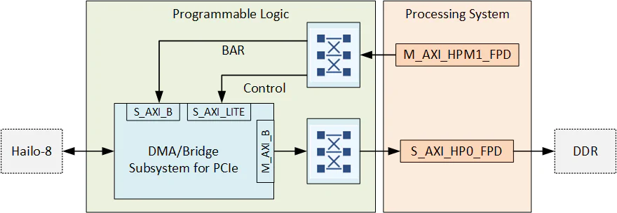
In this design, the Hailo-8 AI accelerator connects to the Zynq UltraScale+ through a single lane PCIe interface. To implement the PCIe root complex, we used the DMA/Bridge Subsystem for PCI Express IP.
The PetaLinux projects in this design include the recipes for various Hailo software packages including the PCIe driver and Hailo TAPPAS. The beautiful thing about the Hailo-8 AI accelerator is that Hailo has provided all of the drivers and software required. It’s seamlessly integrated with GStreamer so once you have your model, it’s super easy to get it running.
The best way to understand what’s happening under the hood of this system is to look at the end-to-end pipeline. The diagram below illustrates the flow of image frames from the source (Raspberry Pi cameras) to the sink (DP monitor). At each interface, I’ve labelled the pixel format and the resolution of the frames going through. By the way, a diagram like this is also very useful for spotting bottlenecks - notice how many times the images have to be written to memory and read back, and the throughput that requires.
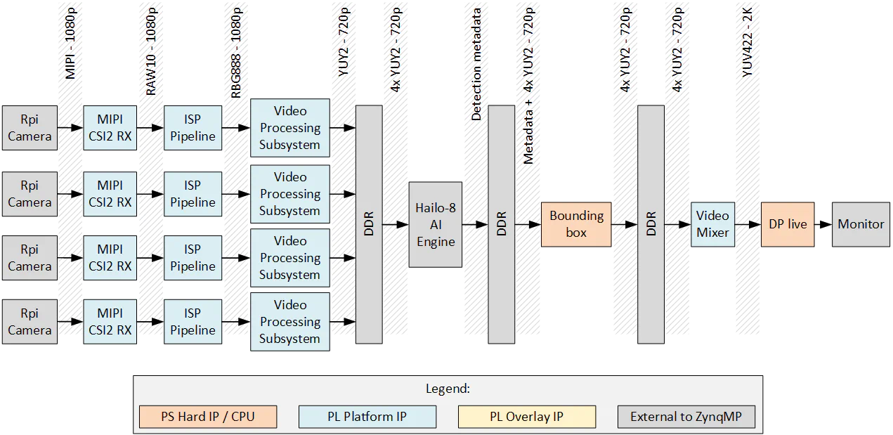
Here is a description of the flow of image frames through the system:
If you’ve used Raspberry Pi cameras before, you might know that the IMX219 image sensor can support 720p natively. So why then are we requesting 1080p from the cameras, only to scale them down to 720p with the Video Processing Subsystem? The reason is that the Linux driver for IMX219 does not support 720p resolution (not yet anyway), so we have to start at 1080p and scale down to the resolution that our AI model was trained for.
The hardware that you will need to run this demo are listed below:
To see the best performance of this demo, you should use a monitor with a resolution of at least 2560x1440. This resolution allows the four 720p video streams to be displayed in the four quadrants of the monitor without any scaling. You can use either a DisplayPort monitor, or a HDMI monitor with DisplayPort-to-HDMI adapter. If you decide to use a DisplayPort-to-HDMI adapter, be aware that the majority of adapters I tested did not work with the ZCU106. AMD Xilinx is aware of this issue but at the time of writing this they have not provided a list of recommended adapters. I have named and linked below to the adapter that I found to work. I have no affiliation with the company that makes the adapter or the monitor.
In this project we use the RPi Camera FMC and the FPGA Drive FMC Gen4, both connected to the FMC connectors on the ZCU106. Each of these boards have different VADJ working ranges, as shown in the table below:
| FMC | VADJ | ZCU106 connector |
|---|---|---|
| RPi Camera FMC | 1.2V | HPC0 |
| FPGA Drive FMC Gen4 | 1.2-3.3V | HPC1 |
Both FMC boards have an EEPROM that is programmed with it’s specific voltage requirements, and the ZCU106 board is designed to read those EEPROMs and settle on a voltage that they both can accept: 1.2VDC. In order to ensure that this process runs smoothly, there are two things that need to be corrected first:
If you are using FPGA Drive FMC Gen4 (OP063) with serial number in the range of 630000 to 630209, you will need to update it’s EEPROM contents with the latest binary. This can be done using the latest Opsero FMC EEPROM Tool. These earlier units were programmed to accept a voltage of 1.8V only. The update ensures that the FMC card will accept a voltage between 1.2V and 3.3V, which is the entire operable range of the FMC card.
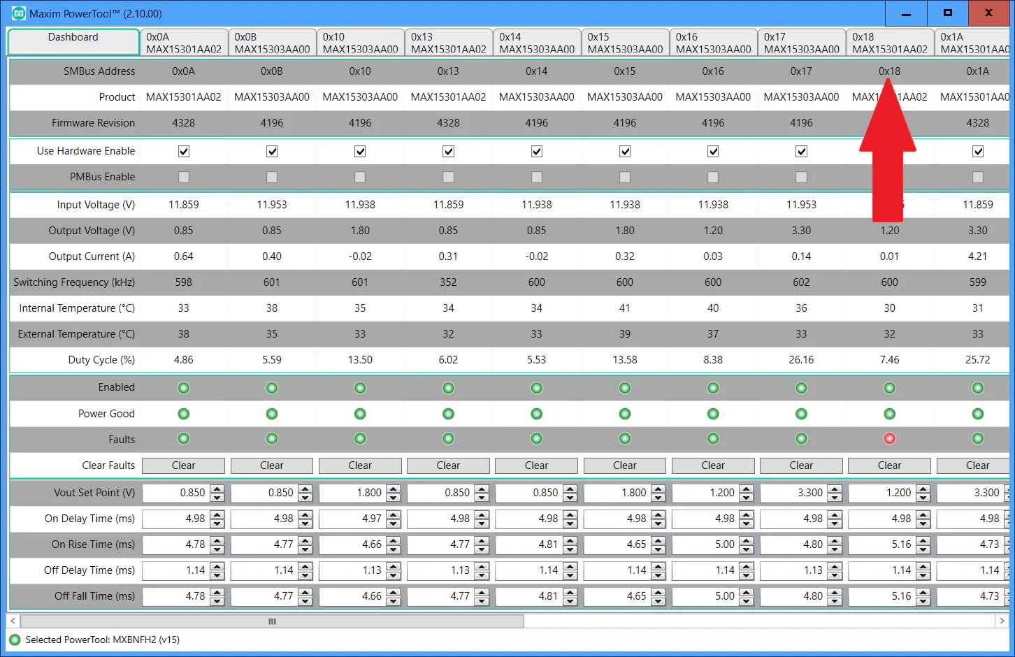
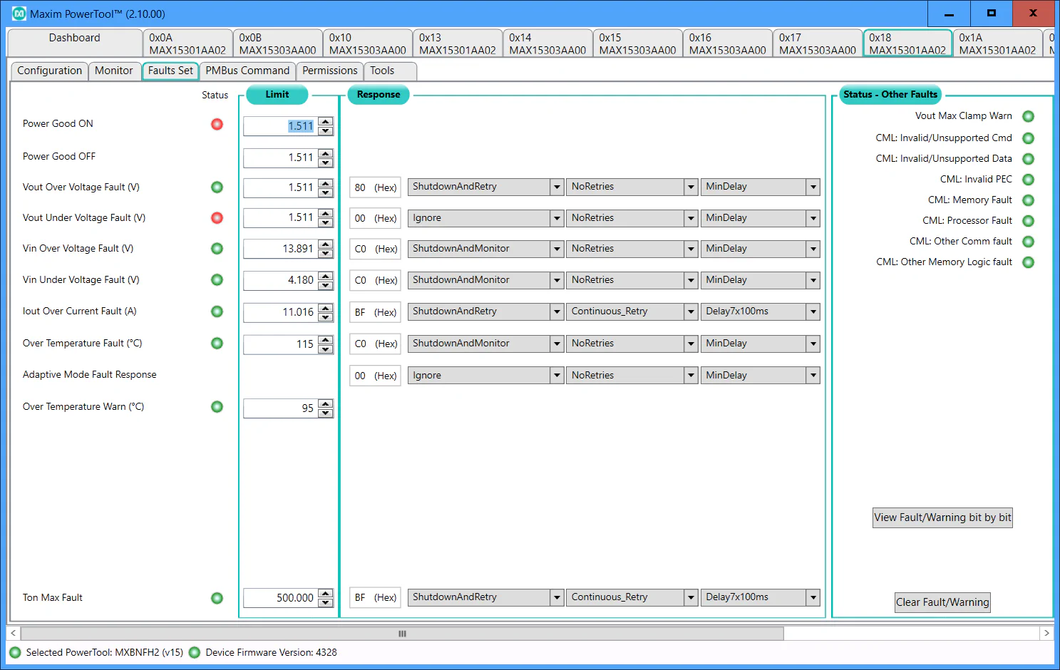
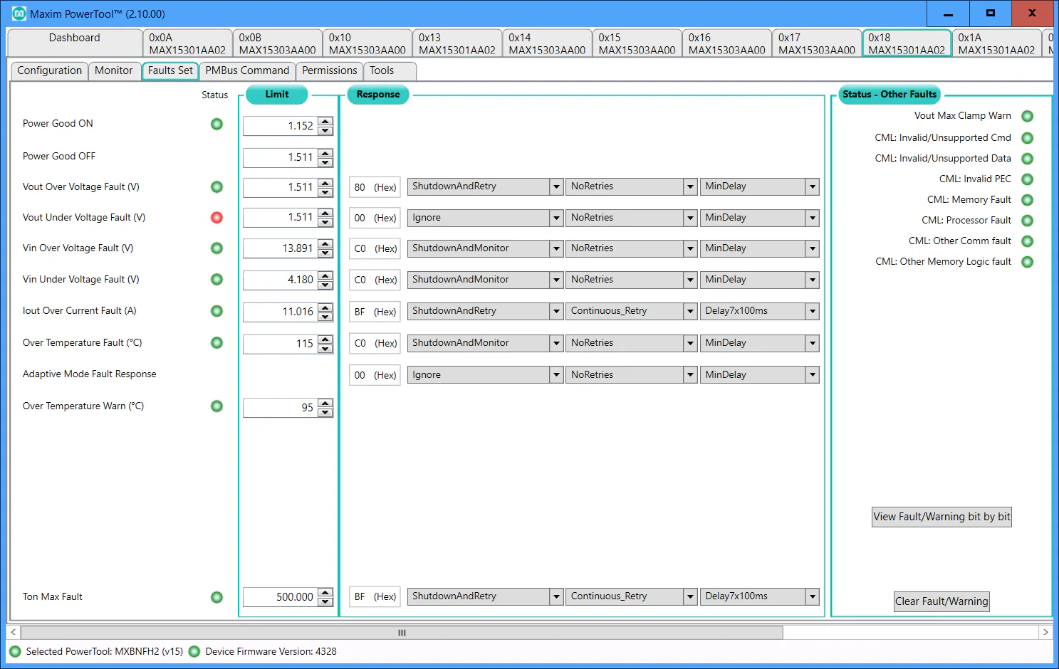
We have to do a slight adjustment to one of the power controllers on the ZCU106 in order to allow it to supply a voltage of 1.2V to the FMC cards. The reason is that the regulator (or more specifically the Digital POL Controller MAX15301, U63) that generates VADJ (the FMC card’s I/O voltage) was configured by default with a “Power Good ON” limit of 1.511V, meaning that any voltage output below 1.511V would trigger a fault.
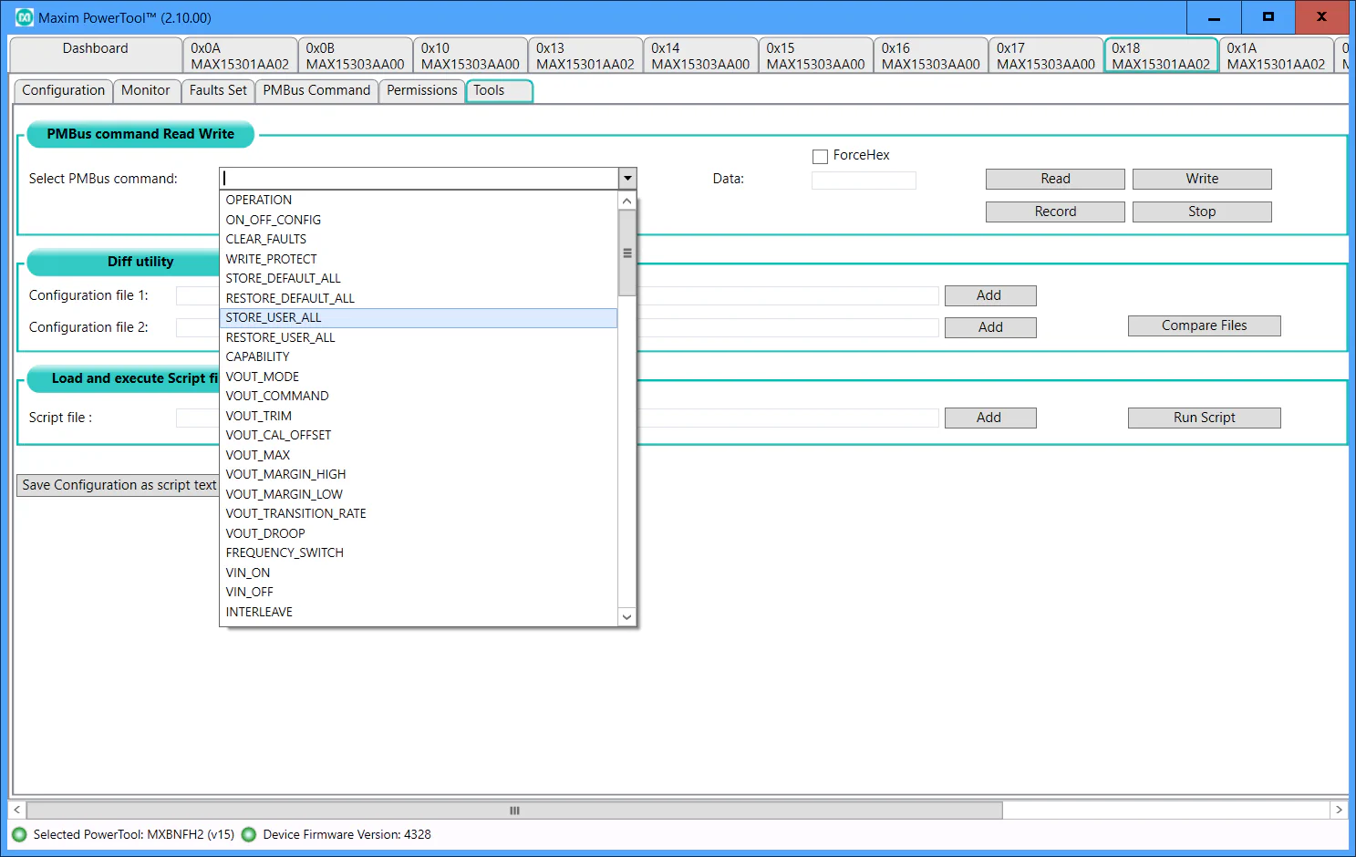
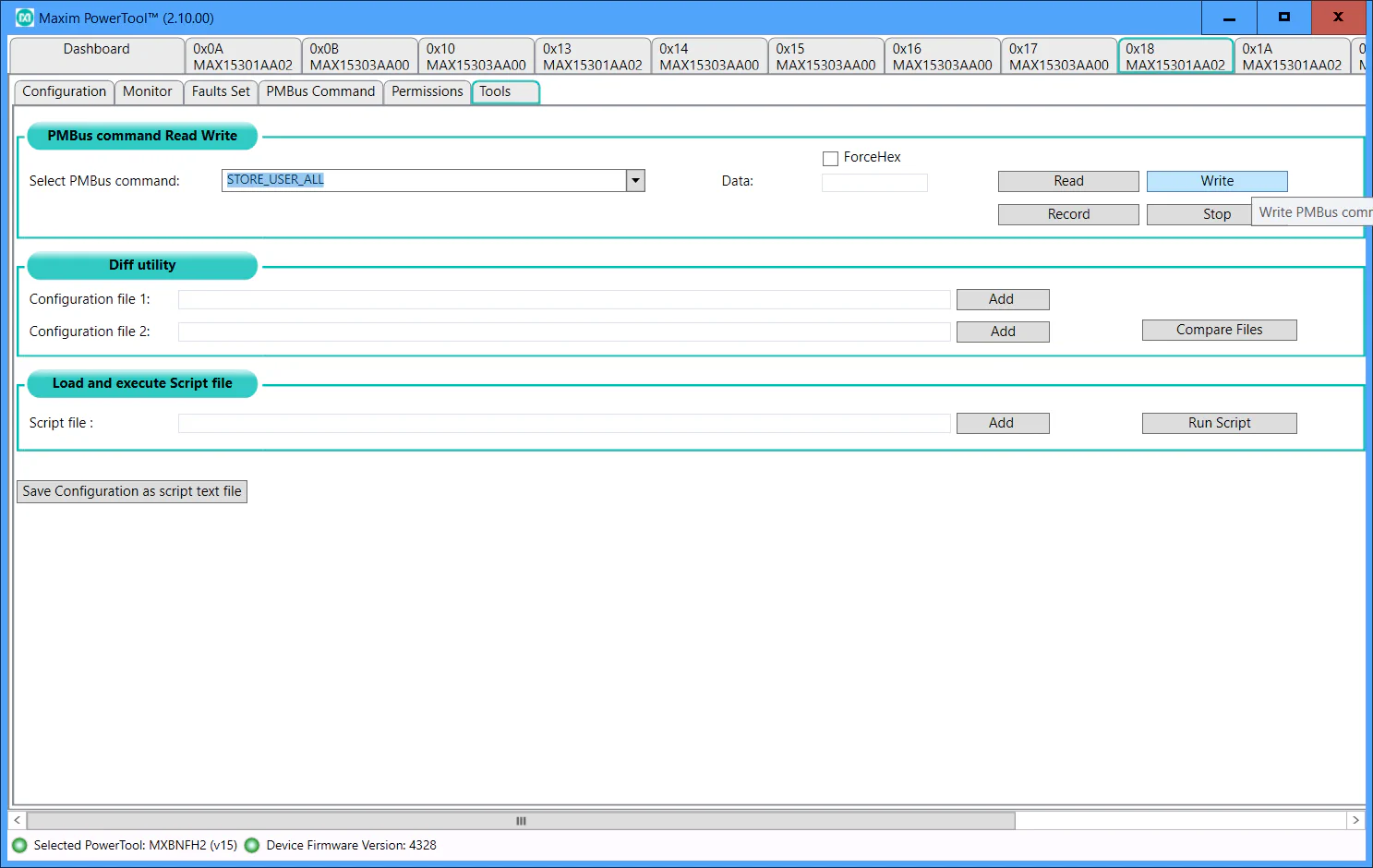
To change this limit, you need to do the following:
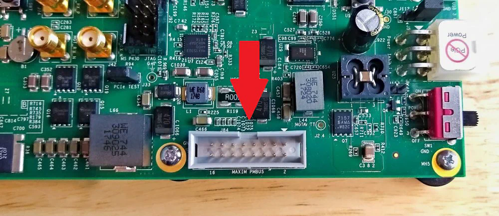
0x18
Now when the board is power cycled, and both FMC cards are connected, you should see that VADJ is powered up at 1.2V on both FMC cards. You can test this quickly by plugging in both FMC cards and powering up the board in JTAG mode (SW6 set to ON-ON-ON-ON). If you see the “POWER” LEDs of both FMC cards light up, then you’re good to go. Note that the FPGA Drive FMC Gen4 has a RED power LED - don’t confuse this with a fault.
The following instructions will show you how to setup the hardware to be able to run this demo. I suggest you follow the instructions in the order that they are written.
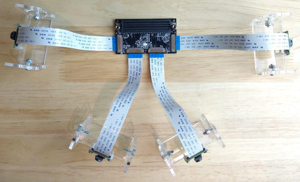
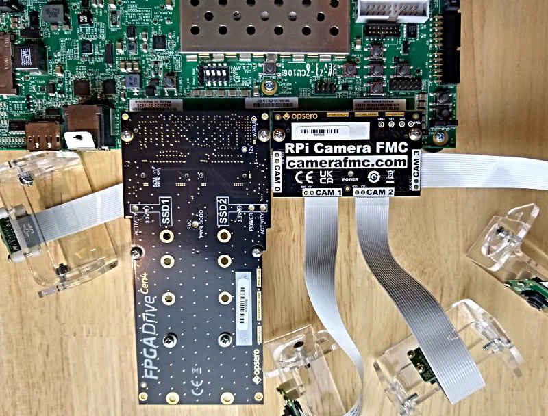
To setup the RPi Camera FMC, I suggest that you first attach the 4x RPi cameras as shown in the image below. Make sure that each of the flex cables are firmly locked into place by pushing in the fastening tabs. Make sure that the blue sides of the flex cables are pointed upwards, just like in the image.
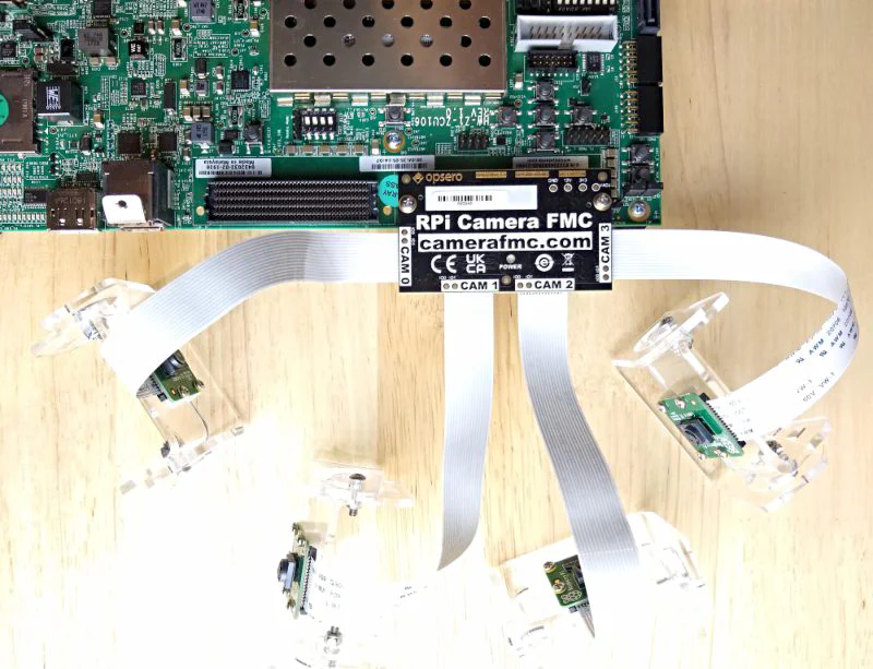
Carefully turn over the FMC card and plug it into the HPC0 connector of the ZCU106 board as shown below. I prefer to do it this way because it’s more of a challenge to attach the cameras once the FMC card is plugged into the carrier.
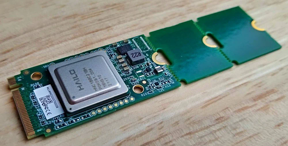
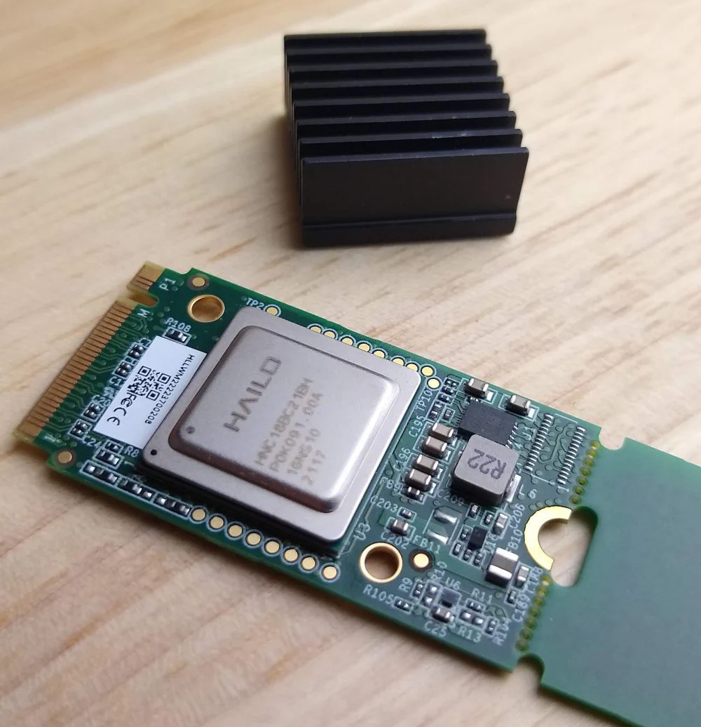
You will need to attach a heat sink to the Hailo-8. I have used a 20x20x10mm heatsink and an adhesive thermal pad from Digikey:
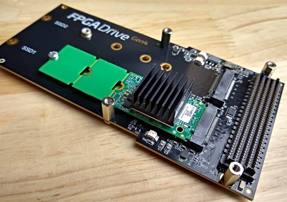
Insert the Hailo-8 module into slot 1 (J2) of the FPGA Drive FMC Gen4 as shown below.
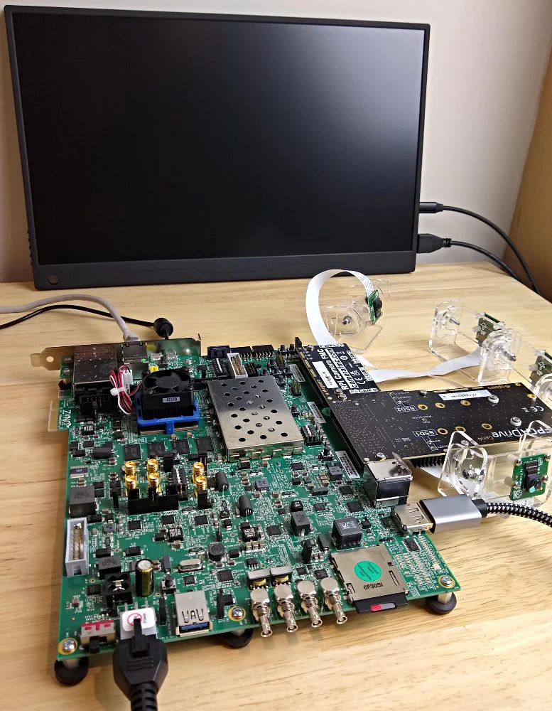
Carefully plug the FMC card into the HPC1 connector of the ZCU106 board as shown below. When doing this, make sure that you support the ZCU106 board from the underside while you apply downward pressure on the FMC card. You don’t want the ZCU106 PCB to bend as you apply pressure.
Make the following remaining connections to the ZCU106 board:
Connect the DisplayPort monitor (or HDMI monitor with DP-to-HDMI adapter as in our case)
Connect the USB-UART port to your computer (we use it as a PetaLinux terminal)
Connect the power supply
Optional: Connect the Ethernet port to your network router if you need network connectivity for SSH access or anything else
The resulting setup should look like this.
As this project is built on PetaLinux, you will need a Linux machine to build it. The machine should have the following tools installed:
The source code for this design is managed in a
Github repo.
The repo contains submodules so remember to use the --recursive option when cloning. To clone the repo, run:
git clone --recursive https://github.com/fpgadeveloper/zynqmp-hailo-ai.gitNow checkout the v2022.1 tag:
cd zynqmp-hailo-ai
git checkout v2022.1
Then source the Vivado and PetaLinux tools:
source <path-to-petalinux>/2022.1/settings.sh
source <path-to-vivado>/2022.1/settings64.sh
To build all parts of the project, including Vivado project, accelerator kernel and PetaLinux, run the following:
cd PetaLinux
make petalinux TARGET=zcu106
The whole build process takes a couple hours on a good machine.
The PetaLinux project that we just built is configured to boot from the SD card, and to store the root filesystem on the SD card. So we need to create two partitions on the SD card: one for the boot files and another for the root file system. We then need to copy the boot files and root file system to the corresponding partitions.
dmesg command. The SD card should be found at the
end of the log, and it’s device name should be something like /dev/sdX, where X is a letter such as a,b,c,d, etc. Note that
you should replace the X in the following instructions.Run fdisk by typing the command (replace sdX with the correct device name):
sudo fdisk /dev/sdXMake the boot partition: type n to create a new partition, then type p to make it primary, then use the default
partition number and first sector. For the last sector, type +1G to allocate 1GB to this partition.
Make the boot partition bootable by typing a
Make the root partition: typing n to create a new partition, then type p to make it primary, then use the default
partition number, first sector and last sector.
Save the partition table by typing w
Format the boot partition (FAT32) by typing:
sudo mkfs.vfat -F 32 -n boot /dev/sdX1Format the root partition (ext4) by typing:
sudo mkfs.ext4 -L root /dev/sdX2Copy the boot files to the boot partition of the SD
card: Assuming the boot partition was mounted to /media/user/boot, follow these instructions:
cd /media/user/boot/
sudo cp <git-repo-path>/PetaLinux/zcu106/images/linux/BOOT.BIN .
sudo cp <git-repo-path>/PetaLinux/zcu106/images/linux/boot.scr .
sudo cp <git-repo-path>/PetaLinux/zcu106/images/linux/image.ub .
sudo cp <git-repo-path>/VitisAccel/zcu106_container/dpu.xclbin .
If you’re using the pre-built boot files, the relevant files are in the boot folder; just copy them over.
Create the root file system by extracting the rootfs.tar.gz file to the root partition. Assuming the root partition was
mounted to /media/user/root, follow these instructions:
cd /media/user/root/
sudo cp <git-repo-path>/PetaLinux/zcu106/images/linux/rootfs.tar.gz .
sudo tar xvf rootfs.tar.gz -C .
sync
If you’re using the pre-built boot files, the rootfs.tar.gz file is in the root folder, so just copy it over
and extract it.
Once the sync command returns, you will be able to eject the SD card from the machine and plug it into the ZCU106.
root and password root.To display all camera video streams on the monitor, run the command displaycams.sh. To end the demo, press Ctrl-C.
To run YOLOv5 on the Hailo-8, and display the results on the monitor, run the command hailodemo.sh. To end the demo, press Ctrl-C.
I’ve filmed the demo running with the four cameras pointed at different sections of a monitor playing a video of some street scenes. The monitor to the right is displaying the four output video streams with detection results. I filmed the demo in this way, so that you could get a feeling for the output frame rate and the end-to-end latency.
As I mentioned earlier, this demo will be displayed live at the EBV Elektronik booth at Embedded World 2024 on April 9-11. I’ll be there too, so come and say “hi”.
You might have noticed that the Git repository contains designs for the ZCU104 and the Avnet UltraZed-EV Carrier - both of which only have one FMC connector. To make this possible, I’ve come up with a new and exciting product, the M.2 M-key Stack FMC, a way to get more out of FMC. I’ll talk more about this in my next post.