Tutorial Overview
This tutorial is the follow-up to Using AXI Ethernet Subsystem and GMII-to-RGMII in a Multi-port Ethernet design. In this part of the tutorial we will generate the bitstream, export the hardware description to the SDK and then test the echo server application on our hardware. The echo server application runs on lwIP (light-weight IP), the open source TCP/IP stack for embedded systems. Our hardware platform is the Avnet ZedBoard combined with the Ethernet FMC.
Regenerate the Vivado project
Firstly, for those of you who did not follow the first part of this tutorial, we will use the scripts in the Git repository for this project to regenerate the Vivado project. If you followed the first part of the tutorial correctly, you should not need to complete this step. Please note that the Git repository is regularly updated for the latest version of Vivado, so you must download the last “commit” for the version of Vivado that you are using.
- Download the sources from Github here: https://github.com/fpgadeveloper/zedboard-qgige
- Depending on your operating system:
- If you are using a Windows machine, open Windows Explorer, browse to the “Vivado” folder within the sources you just downloaded. Double-click on the
build.batfile to run the batch file. - If you are using a Linux machine, run Vivado and then select Window->Tcl Console from the welcome screen. In the Tcl console, use the
cdcommand to navigate to the “Vivado” folder within the sources you just downloaded. Then typesource build.tclto run the build script.
- If you are using a Windows machine, open Windows Explorer, browse to the “Vivado” folder within the sources you just downloaded. Double-click on the
- Once the script has finished running, the Vivado project should be regenerated and located in the “Vivado” folder. Run Vivado and open the newly generated project.
If you did not follow the first part of this tutorial, you may want to open the block diagram and get familiar with the design before continuing.
Generate the bitstream
When you are ready to generate the bitstream, click “Generate Bitstream” in the Flow Navigator.
Once the bitstream is generated, the following window will appear. Select “View Reports” and click “OK”.

Export the hardware to SDK
When the bitstream has been generated, we can export it and the hardware description to the Software Development Kit (SDK). In the SDK we will be able to generate the echo server example design and run it on our hardware.
- In Vivado, from the File menu, select “Export->Export hardware”.

- In the window that appears, tick “Include bitstream”, select Export to “Local to Project”, and click “OK”.

- From the File menu, select “Launch SDK”.

- In the window that appears, you need to specify the location of the hardware description and the location of the SDK workspace. We specified earlier to generate the hardware description local to the project (including bistream), so the Exported location must be “Local to Project”. By preference, we choose to create the SDK workspace local to the project, but you can change this if you wish. Click “OK”.

At this point, the SDK loads and a hardware platform specification will be created for your design.
Create the Echo Server application
At this point, your SDK workspace should contain only the hardware description and no applications:

We add the echo server application by selecting New->Application Project from the File menu.

In the New Project wizard, we want to name the application appropriately, so type echo_server as the project name then click “Next”.

The next page allows you to create the new application based on a template. Select the “lwIP Echo Server” template and click “Finish”.

The SDK will generate a new application called echo_server and a Board Support Package (BSP) called echo_server_bsp, both of which you will find in the Project Explorer as shown below.

By default, the SDK is configured to build the application automatically.
Modify the application
The echo server template application will be setup to run on the first AXI Ethernet Subsystem block in our design. This corresponds to PORT0 of the Ethernet FMC. We want to add some code to the application to allow us to select a different port if we choose.
- Open the
main.cfile from the echo_server source folder.
- After the last “#include” statement, add the following code:
#include "xlwipconfig.h"

/* Set the following DEFINE to the port number (0,1,2 or 3)
* of the Ethernet FMC that you want to hook up
* to the lwIP echo server. Only one port can be connected
* to it in this version of the code.
*/
#define ETH_FMC_PORT 0

/*
* NOTE: When using ports 0..2 the BSP setting "use_axieth_on_zynq"
* must be set to 1. When using port 3, it must be set to 0.
* To change BSP settings: right click on the BSP and click
* "Board Support Package Settings" from the context menu.
*/
#ifdef XLWIP_CONFIG_INCLUDE_AXIETH_ON_ZYNQ
#if ETH_FMC_PORT == 0
#define EMAC_BASEADDR XPAR_AXIETHERNET_0_BASEADDR  // Eth FMC Port 0
#endif
#if ETH_FMC_PORT == 1
#define EMAC_BASEADDR XPAR_AXIETHERNET_1_BASEADDR  // Eth FMC Port 1
#endif
#if ETH_FMC_PORT == 2
#define EMAC_BASEADDR XPAR_AXIETHERNET_2_BASEADDR  // Eth FMC Port 2
#endif
#else /* XLWIP_CONFIG_INCLUDE_AXIETH_ON_ZYNQ is not defined */
#if ETH_FMC_PORT == 3
#define EMAC_BASEADDR XPAR_XEMACPS_1_BASEADDR  // Eth FMC Port 3
#endif
#endif
- Then go down to where the define
PLATFORM_EMAC_BASEADDRis used, and replace it withEMAC_BASEADDR.
When you save the main.c file, the SDK should automatically start rebuilding the application.
Modify the Libraries
The BSP for this project will also have to be modified slightly. There are a few reasons for these modifications, but we would be going off-track to discuss those reasons in detail at this point. If you’re using a version of Vivado between 2015.4 and 2016.2, you will have to use an earlier commit of the repo and read the the README.md file for instructions on applying the modifications:
If you are using Vivado 2016.3 or a newer version, find the last commit for your version of Vivado and the project repo will contain a copy of the modified source files. You will find the modified library files inside the EmbeddedSw directory of the repo.
I strongly recommend that you perform these modifications to the sources in the Vivado installation files - not the sources in the BSP of your SDK workspace. The reason is that the BSP sources will be written-over with the original sources every time that you re-build the BSP - so you’re better off modifying them at the true source.
Note: These modifications are specific to using the echo server application on the Ethernet FMC. If you are not using the Ethernet FMC, you may not need to make these modifications and you’re better off leaving the library sources as they are.
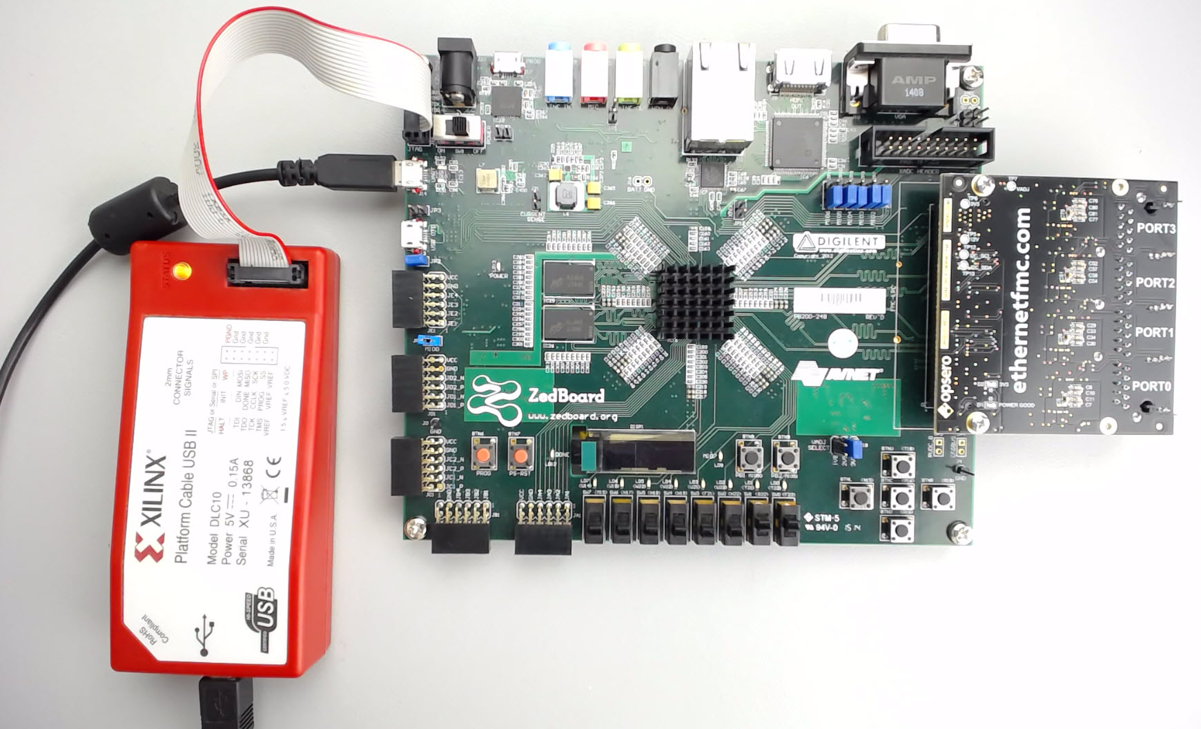
Setup the hardware
To setup our hardware, we need to configure the ZedBoard for configuration by JTAG, we need to set the VADJ voltage to the appropriate value and we need to correctly attach the Ethernet FMC. Follow these instructions to ensure that your setup is correct:
- On the ZedBoard, set the JP7, JP8, JP9, JP10 and JP11 jumpers all to the SIG-GND position. This sets it for configuration by JTAG.

- Set the VADJ select jumper (J18) to either 1.8V or 2.5V, depending on the version of Ethernet FMC that you are using. We are using the 2.5V version.

- Connect the Ethernet FMC to the FMC connector of the ZedBoard. Apply pressure only to the area above and below the connector - you should feel the two connectors “snap” together.

- Now we need to use two screws to fix the Ethernet FMC to the ZedBoard - you should find two M2.5 x 4mm screws included with the ZedBoard. Turn the ZedBoard upside down and use a Phillips head screwdriver to fix the Ethernet FMC to the ZedBoard. Please do not neglect this step, it is very important and will protect your hardware from being damaged in the event that the Ethernet FMC hinges and becomes loose. The FMC connector is not designed to be the only mechanical fixation between the carrier and mezzanine card, the screws are necessary for mechanical and electrical integrity.

- Turn the ZedBoard around so that it is sitting the right way up.
- Connect the USB-UART (J14) to a USB port of your PC.

- Connect a Platform Cable USB II programmer (or similar device) to the JTAG connector. Connect the programmer to a USB port of your PC. Alternatively, if you don’t have a programmer, you can connect a USB cable to the J17 connector of the ZedBoard.

- Connect PORT0 of the Ethernet FMC to a gigabit Ethernet port of your PC.

- Now plug the ZedBoard power adapter into a wall socket and then into the ZedBoard.

- Switch ON the power to the board. You should see the “POWER” LED on the ZedBoard turn on.
Test the Echo Server on hardware
To be able to read the output of the echo server application, we need to use a terminal program such as Putty. Use the following settings:
- Comport - check your device manager to find out what comport the ZedBoard popped up as. In my case, it was COM16 as shown below.

- Baud rate: 115200bps
- Data: 8 bits
- Parity: None
- Stop bits: 1
With the terminal program open, we can now load our ZedBoard with the bitstream and then run the echo server application.
- In the SDK, from the menu, select Xilinx Tools->Program FPGA.

- In the Program FPGA window, we select the hardware platform to program. We have only one hardware platform, so click “Program”.

- The bitstream will be loaded onto the Zynq and we are ready to load the software application. Select the
echo_serverfolder in the Project Explorer, then from the menu, select Run->Run.
- In the Run As window, select “Launch on Hardware (GDB)” and click “OK”.

- The application will be loaded on the Zynq PS and it will be executed. The terminal window should display this output from the echo server:

The output indicates that:
- The PHY auto-negotiation sequence has completed
- The auto-negotiated link-speed is 1Gbps
- The DHCP timeout was reached, indicating that the application was not able to get an IP address from a DHCP server
- The auto-assigned IP address is 192.168.1.10
Now that the application is running successfully, we can test the echo server by sending packets from our PC to the ZedBoard and looking at what gets sent back.
Ping Test
All Ethernet devices are required to respond to ping requests, so this is a very simple and easy test to perform using your computer. Just open a command window and type ping 192.168.1.10.

Packet Echoing
To test that the echo server is actually doing its job and echoing received packets, you will have to install software that allows you to send and receive arbitrary packets. The software that I use is called Packet Sender and can be downloaded here. Once the software is installed, follow the instructions below to send and receive packets:
- Run Packet Sender.
- Create a new packet to send using these parameters and then click “Save”:
- Name: Test packet
- ASCII: follow the white rabbit
- IP Address: 192.168.1.10
- Port: 7
- Resend: 0

- The packet details will be saved in the Packets tab, and we can now click on the “Send” button to send that packet whenever we want. Click “Send” and see what happens.

- If everything went well, the Traffic Log tab should display two packets: one sent by our computer and one received by our computer. They should both occur almost instantaneously, so if you only see one, you’ve probably got a problem with your setup.

If you want to experiment, you can play around with the software by sending more packets, or different kinds of packets.
Changing ports
So far we’ve been using PORT0 of the Ethernet FMC to test the echo server, but suppose we wanted to use one of the other ports 1,2 or 3. You can configure the port on which to run lwIP by setting the ETH_FMC_PORT define that we added earlier to the main.c file of the SDK application. Valid values for ETH_FMC_PORT are 0,1,2 or 3.
One other thing to be aware of is the BSP setting called use_axieth_on_zynq. This parameter specifies whether the BSP will be used with AXI Ethernet Subsystem or with something else: Zynq GEM, Ethernet lite, etc. Remember that in our Vivado design we connected ports 0, 1 and 2 to an AXI Ethernet Subsystem block, and we connected port 3 to the GEM1 of the Zynq PS. Therefore, when selecting the port on which you wish to run lwIP, remember to correctly set the use_axieth_on_zynq parameter:
- When using ports 0..2 the BSP setting
use_axieth_on_zynqmust be set to 1. - When using port 3, the BSP setting
use_axieth_on_zynqmust be set to 0.
The application will not compile if the correct BSP settings have not been set. To change BSP settings: right click on the BSP and click Board Support Package Settings from the context menu.
What now?
The echo server application is actually a very good starting place for developing Ethernet applications on the ZedBoard or other Xilinx FPGAs. Here are some potential ways you could “tweek” the echo server application to be useful for other things:
- Allow your FPGA designs to be controlled by TCP commands sent from a PC over an Ethernet cable - or over the Internet.
- Send data over TCP from your PC to your FPGA and leverage the FPGA for hardware acceleration.
- Connect your FPGA to the Internet and design a high-performance IoT device.
Alternatively, if you’re interested in using Linux, take a look at this tutorial on bringing up multiple Ethernet ports in PetaLinux.
Source code Git repository
Below are the links to the source code Git repositories. There is a version of the project for the ZedBoard and the MicroZed. There is also a version that uses only the AXI Ethernet Subsystem IP.
- ZedBoard using GMII-to-RGMII and AXI Ethernet Subsystem
- ZedBoard using AXI Ethernet Subsystem only
- MicroZed using GMII-to-RGMII and AXI Ethernet Subsystem
If you enjoyed this tutorial or if you run into problems using it, please leave me a comment below.