Connecting an SSD to an FPGA running PetaLinux

Connecting an SSD to an FPGA running PetaLinux

This is the final part of a three part tutorial series on creating a PCI Express Root Complex design in Vivado and connecting a PCIe NVMe solid-state drive to an FPGA.

In this final part of the tutorial series, we’ll start by testing our hardware with a stand-alone application that will verify the status of the PCIe link and perform enumeration of the PCIe end-points. We’ll then run PetaLinux on the FPGA and prepare our SSD for use under the operating system. PetaLinux will be built for our custom hardware using the PetaLinux SDK and the Vivado generated hardware description. Using Linux commands, we will then create a partition, a file system and a file on the solid-state drive.

[Read More]
nvme  pcie  ssd  popular 

Zynq PCI Express Root Complex design in Vivado

This is the second part of a three part tutorial series in which we will create a PCI Express Root Complex design in Vivado with the goal of connecting a PCIe NVMe solid-state drive to our FPGA.

In this second part of the tutorial series, we will build a Zynq based design targeting the PicoZed 7Z030 and PicoZed FMC Carrier Card V2. In part 3, we will then test the design on the target hardware by running a stand-alone application which will validate the state of the PCIe link and perform enumeration of the PCIe end-points. We will then run PetaLinux on the FPGA and prepare our SSD for use under the operating system.

[Read More]

Microblaze PCI Express Root Complex design in Vivado

This is the first part of a three part tutorial series in which we will go through the steps to create a PCI Express Root Complex design in Vivado, with the goal of being able to connect a PCIe end-point to our FPGA. We will test the design on hardware by connecting a PCIe NVMe solid-state drive to our FPGA using the FPGA Drive adapter.

Part 1: Microblaze PCI Express Root Complex design in Vivado (this tutorial)

[Read More]

FPGA Drive Board Bring-up

FPGA Drive Board Bring-up

Bring-up of the first FPGA Drive with the Kintex-7 KC705 Evaluation board went nice and smoothly today. In the photo below you’ll see the KC705 and FPGA Drive adapter which is loaded with a Samsung V-NAND 950 Pro. The solid-state drive is an M.2 form factor, NVM Express, 4-lane PCI Express drive with 256GB of storage.

A little intro to NVM Express. NVM Express or NVMe is an interfacing specification for accessing SSDs over a PCI Express bus. By connecting the SSD over PCIe, it has a direct connection to the CPU which results in lower latency when compared to SATA drives, as well as increased throughput and potential for scaling (just add more lanes). PCIe SSDs can use the older AHCI interfacing standard, but due to the way that standard was designed, it can’t fully exploit the potential of modern SSDs. The NVMe specification was designed from the ground up to solve this problem.

[Read More]
nvme 

Xilinx reveals Virtex Ultrascale Board for PCI Express applications

Xilinx just released a video presenting the next-generation of All Programmable devices and dev environments. It’s a quick look at where technology is going and particularly where FPGAs are going to make their mark.

Of particular interest to me were the images of a Virtex Ultrascale PCI Express board at 2:45 in the video. This board appears to have both the PCIe gold-finger edge connector and a PCIe saddle-mount socket connector, so it could be used as either the PCIe end-point or the root complex - or maybe both at the same time. Most of Xilinx’s dev boards have the PCIe edge connector but as far as I know, the only FPGA dev board with a PCIe socket is the Mini-ITX from Avnet.

[Read More]

Comparison of 7 Series FPGA boards for PCIe

Comparison of 7 Series FPGA boards for PCIe

One of my most common customer requests is to speed up execution of a software application using FPGA hardware acceleration. If the application runs on a PC or server, you can achieve impressive performance gains by using off-the-shelf FPGA development boards for PCI Express.

Here is a comparison of the available 7 Series FPGA boards for PCI Express applications:

AC701 Artix-7 KC705 Kintex-7 VC707 Virtex-7 VC709 Virtex-7
$1295 $1695 $3495 $4995
XC7A200T-2FBG676C XC7K325T-2FFG900C XC7VX485T-2FFG1761 XC7VX690T-2FFG1761C
4-lane Gen2 PCIe 8-lane Gen2 PCIe 8-lane Gen2 PCIe 8-lane Gen3 PCIe
1GB DDR3 SODIMM 1GB DDR3 SODIMM 1GB DDR3 SODIMM 4GB DDR3 SODIMM x2
8Kb EEPROM 8Kb EEPROM 8Kb EEPROM 1KB EEPROM
No BPI Flash 128MB BPI Flash 128MB BPI Flash 32MB BPI Flash
32MB Quad SPI 16MB Quad SPI 16MB Quad SPI No Quad SPI Flash
SD Card slot SD Card slot SD Card slot No SD
No LPC FMC 1x LPC FMC No LPC FMC No LPC FMC
1x HPC FMC (*) 1x HPC FMC (*) 2 x HPC FMC 1x HPC FMC (*)
1x SFP 1x SFP+ 1x SFP+ 4x SFP/SFP+
1GB Ethernet 1GB Ethernet 1Gb Ethernet No Ethernet
No USB No USB No USB No USB
UART over USB UART over USB UART over USB UART over USB
HDMI out HDMI out HDMI out No Video
XADC header XADC header AMS port No Analog
  • (*) Note: These HPC FMC connectors are only partially populated which means that they wont be able to support all standard FMCs.
  • There are many more FPGA boards for PCIe on the market, but I chose to limit the comparison to those that are more strongly supported by Xilinx.

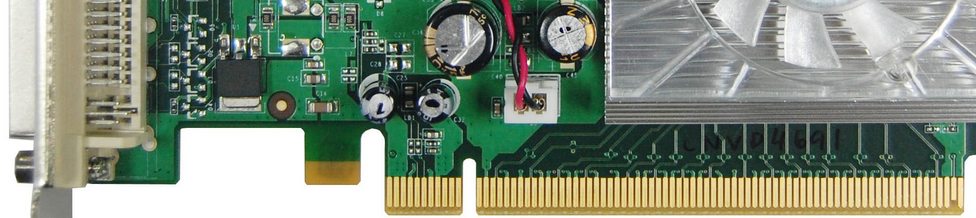
The reason these types of boards are so useful in the hardware acceleration space is because PCI Express is the highest bandwidth, lowest latency link that you can have between a PC’s CPU and an external FPGA. There’s no use shipping off work to an FPGA if the time it takes the data to get there and back is more than the time saved through improved processing efficiency.

[Read More]