Title here
Summary here
Creating a Vivado design for the MYIR Z-turn Zynq SoM and running hello world and lwIP echo server
October 18, 20173 minutes
Updated video tutorial on using the AXI DMA IP in Vivado 2017.2 with a MicroZed Zynq design
October 11, 201716 minutes
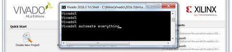
A cheat sheet of useful Tcl commands and tricks for automating Vivado and Xilinx SDK workflows
November 1, 20165 minutes
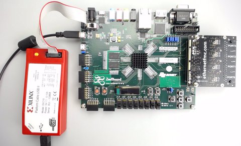
Building a custom PetaLinux image for the ZedBoard with four extra Ethernet ports via Ethernet FMC.
May 4, 20169 minutes
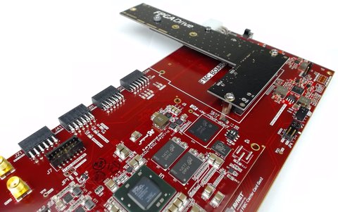
Tutorial on connecting an NVMe SSD to an FPGA and accessing it from PetaLinux using FPGA Drive.
April 15, 201614 minutes
Tutorial on creating a Zynq-based PCIe Root Complex design in Vivado to connect an NVMe SSD.
April 14, 201613 minutes
Tutorial on creating a Microblaze-based PCIe Root Complex design in Vivado to connect an NVMe SSD.
April 13, 201618 minutes
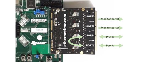
Testing a multi-port Ethernet design by running a lwIP echo server on the ZedBoard with Ethernet FMC.
January 5, 201611 minutes
Designing a transparent Ethernet pass-through in Vivado as the foundation for an FPGA network tap.
December 29, 20157 minutes
Building a multi-port Gigabit Ethernet design in Vivado using AXI Ethernet and GMII-to-RGMII IP cores.
December 8, 201516 minutes